Image Display Device, Image Display Method, Image Display Program, And Computer -Readable Storage Medium

a display device and image technology, applied in the field of image display, can solve the problems of large amount of labor for apparatus without pointing devices, large portion of display images to be hidden, and inconvenient us

Inactive Publication Date: 2008-04-10
SHARP KK
View PDF5 Cites 9 Cited by
  • Summary
  • Abstract
  • Description
  • Claims
  • Application Information

AI Technical Summary

Benefits of technology

[0011] This makes it possible to minimize, regardless of how the outer edge of the display region and the display image are related in size to each other, a portion of the display image which portion is hidden by moving out of the display region when the display image has ...

Problems solved by technology

That is, the rotation may cause a large portion of the display image to be hidden.
Therefore, an apparatus having no pointing device requires a large amount of labor in designating a central location of rotation, a...

Method used


Image

  • Image Display Device, Image Display Method, Image Display Program, And Computer -Readable Storage Medium
  • Image Display Device, Image Display Method, Image Display Program, And Computer -Readable Storage Medium
  • Image Display Device, Image Display Method, Image Display Program, And Computer -Readable Storage Medium

Examples


embodiment 1

[0035] An embodiment of the present invention will be described below with reference to FIGS. 1 through 7.

[0036] As shown in FIG. 1, a display device 1 according to the present invention includes a display section 10, an input section 11, a display control section 12, and a storage section 13.

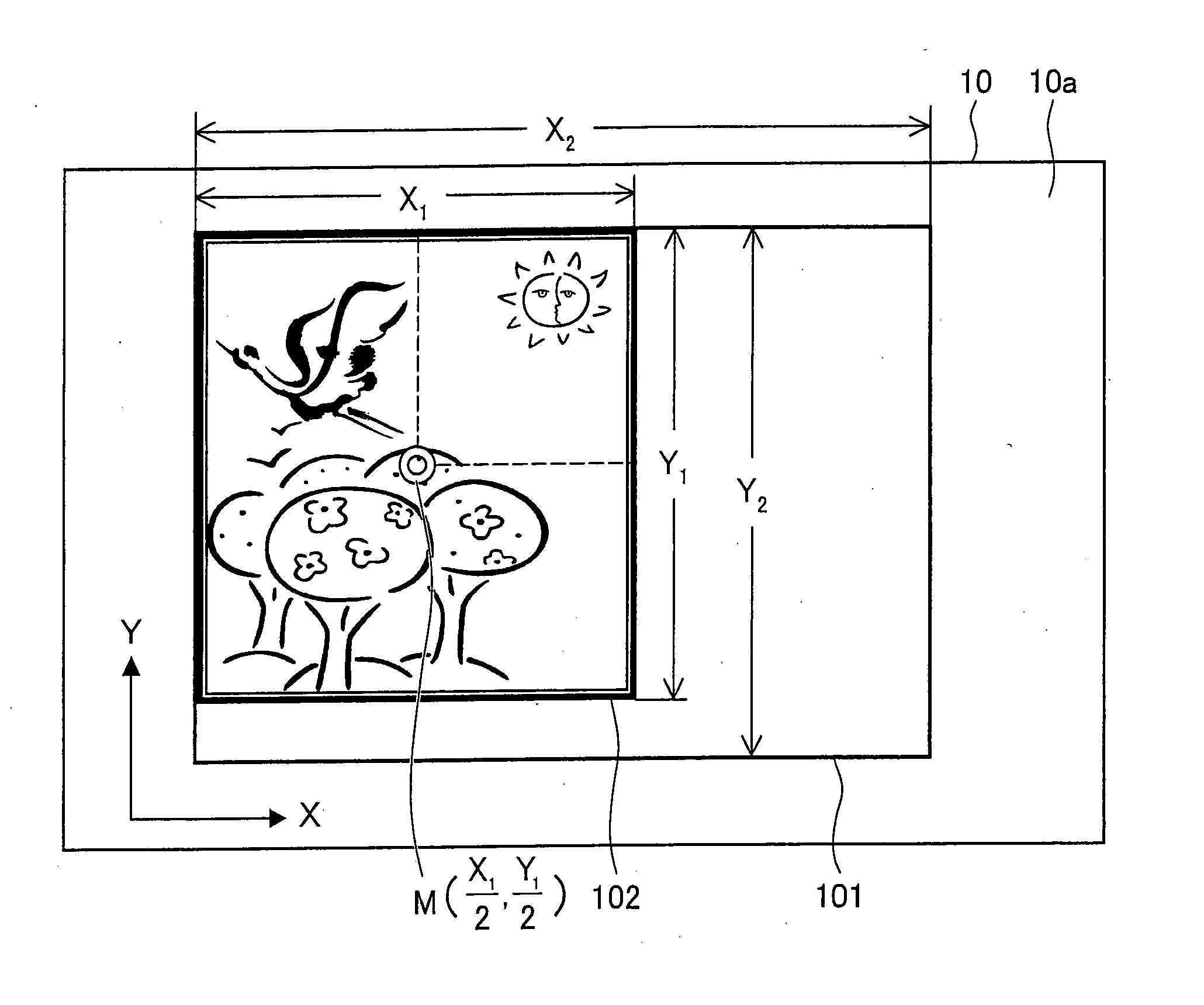
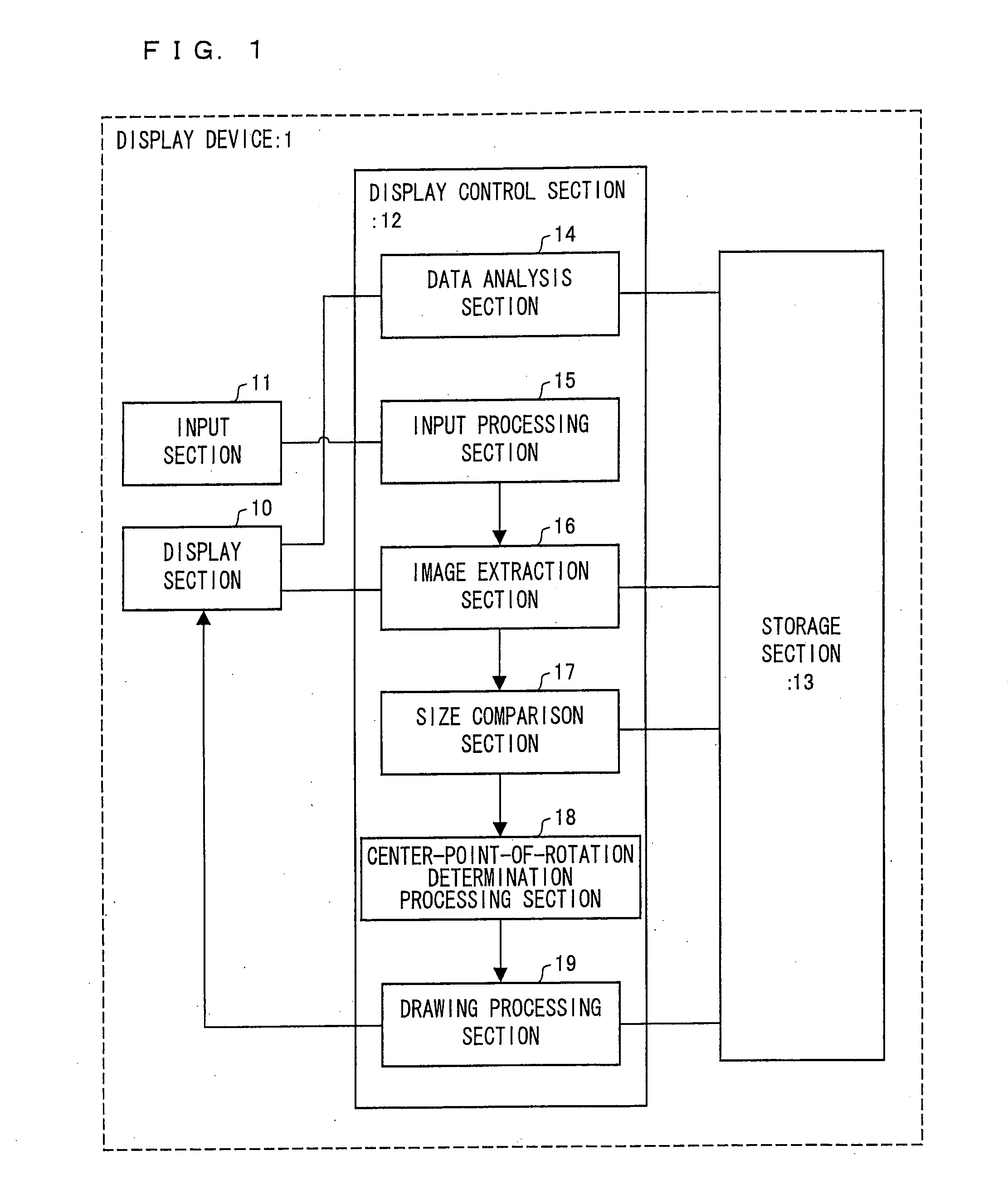
[0037] As shown in FIG. 2, the display section 10 is display means for displaying a display frame (outer edge of a display region) 101 and a display image 102 in a display feasible region 10a. The display section 10 is constituted by a flat display such as a liquid crystal display device.

[0038] Further, the display section 10 is designed to display at least part of the display image 102 in the display frame 101 of the display feasible region 10a.

[0039]FIG. 2 shows a case where the display image 102 is smaller than the display frame 101. Further, FIG. 2 also shows an example in which the whole of the display image 102 is displayed in the display section 10 and in which there are margins at t...

embodiment 2

[0087] Another embodiment of the present invention will be described below with reference to the drawings. Components having the same functions as those described above in Embodiment 1 are given the same reference numerals, and a description thereof is omitted. A display device 2 according to the present embodiment is different in arrangement from the display device 1, shown in Embodiment 1, in terms of the display control section 12 and the storage section 13, but is identical to the display device 1 in terms of the other arrangements.

[0088] As shown in FIG. 8, a display control section 212 of the present embodiment is arranged by adding a display processing section 220 to Embodiment 1 described above. Further, in the present embodiment, the targets of comparison compared by the size comparison section 17 described in Embodiment 1 are changed. Furthermore, as shown in FIG. 9, a storage section 213 of the present embodiment is arranged such that the display frame storage section 26...

embodiment 3

[0113] Another embodiment of the present invention will be described below with reference to the drawings. Components having the same functions as those described above in Embodiment 2 are given the same reference numerals, and a description thereof is omitted. A display device 3 according to the present embodiment is different in arrangement from the display device 2, shown in Embodiment 2, in terms of the display control section 212. The display device 3 according to the present embodiment is arranged so that the user can select a method for determining a center point. Further, as shown in FIG. 14, the display device 3 according to the present embodiment is different in arrangement from the display device 2, shown in Embodiment 2, in terms of the storage section 213. Specifically, in a storage section 313 of the display device 3 according to the present embodiment, the partial display-image vertical-information storage section 231 and the partial display-image horizontal-informati...


PUM


Abstract

An image display device (1) of the present invention is an image display device having a function of rotating a display image, the image display device including: a size comparison section (17) for making a comparison (i) between a vertical length of an outer edge of a display region in which the display image is displayed and a vertical length of the display image and (ii) between a horizontal length of the outer edge of the display region in which the display image is displayed and a horizontal length of the display image; and a center-point-of-rotation determination section (18) for determining a center point of rotation of the display image in accordance with a result of the comparison made by the size comparison section (17). This makes it possible to provide a display device (i) which minimizes, regardless of how a display frame and a display image are related in position and size to each other, a portion of the display image which portion is to be hidden when the display image has been rotated and (ii) which can be easily employed in a rotation process.

Description

TECHNICAL FIELD [0001] The present invention relates to an image display devices having a function of rotating a display image. BACKGROUND ART [0002] Generally, a display device that displays an image and / or a figure has a function of rotating a display image so that a user can easily see the display image. In such a display device, a given point is determined as a center point of rotation, and a display image is rotated on the point. [0003] For example, Publicly-known Document 1 (Japanese Unexamined Patent Application No. 184526 / 1989 (Tokukaihei 1-184526; published on Jul. 24, 1989) discloses an arrangement in which a point at the upper left or lower right of a display screen is set as a center point of rotation, i.e., an arrangement in which a center point of rotation is fixed. [0004] Further, Publicly-known Document 2 (Japanese Unexamined Patent Application No. 109940 / 1999 (Tokukaihei 11-109940; published on Apr. 23, 1999) discloses an arrangement in which a user designates a cen...

Claims


Application Information

Patent Timeline
IPC IPC(8): G09G5/00G06F3/048G06F3/0484
CPCG06T3/60G09G2340/0492G09G2340/0407G09G5/393
Inventor SAKAKURA, KENTARO
Owner SHARP KK
Why Eureka
Try Eureka