

Battery module and method of manufacturing the same
- Summary
- Abstract
- Description
- Claims
- Application Information
AI Technical Summary
Benefits of technology
Problems solved by technology
Method used
Image

Examples
Embodiment Construction
[0027]Hereinafter, exemplary embodiments of the present invention will be described in detail with reference to the attached drawings such that the present invention can be easily put into practice by those skilled in the art. However, the present invention is not limited to the embodiments described herein, but may be embodied in various forms. Elements that do not correspond to the present invention will not be described in order to provide a simplified description of the invention in association with the drawings. Like reference numerals denote like elements throughout the entire specification. Also, elements already well known in the art will not be described in detail.
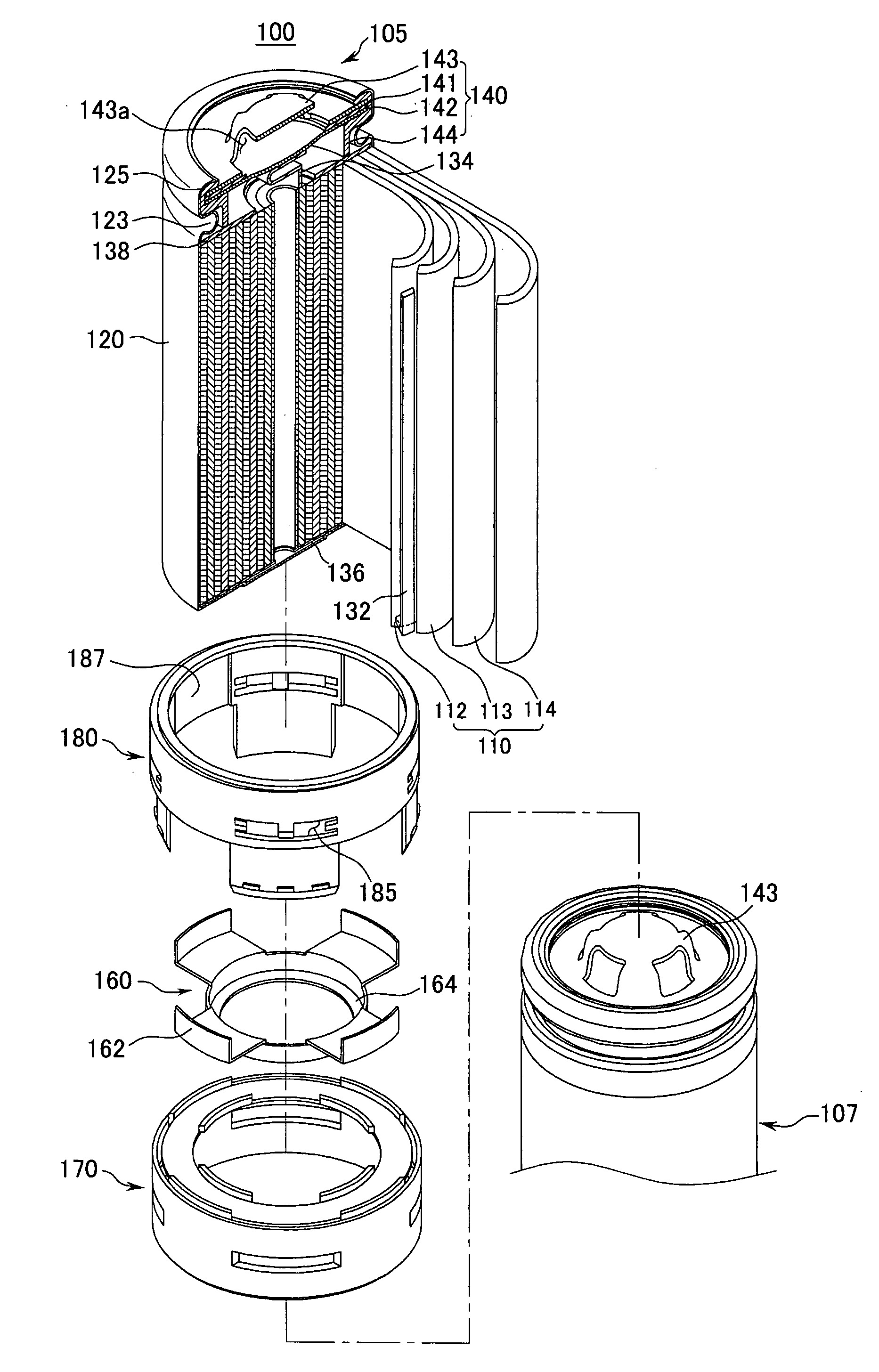
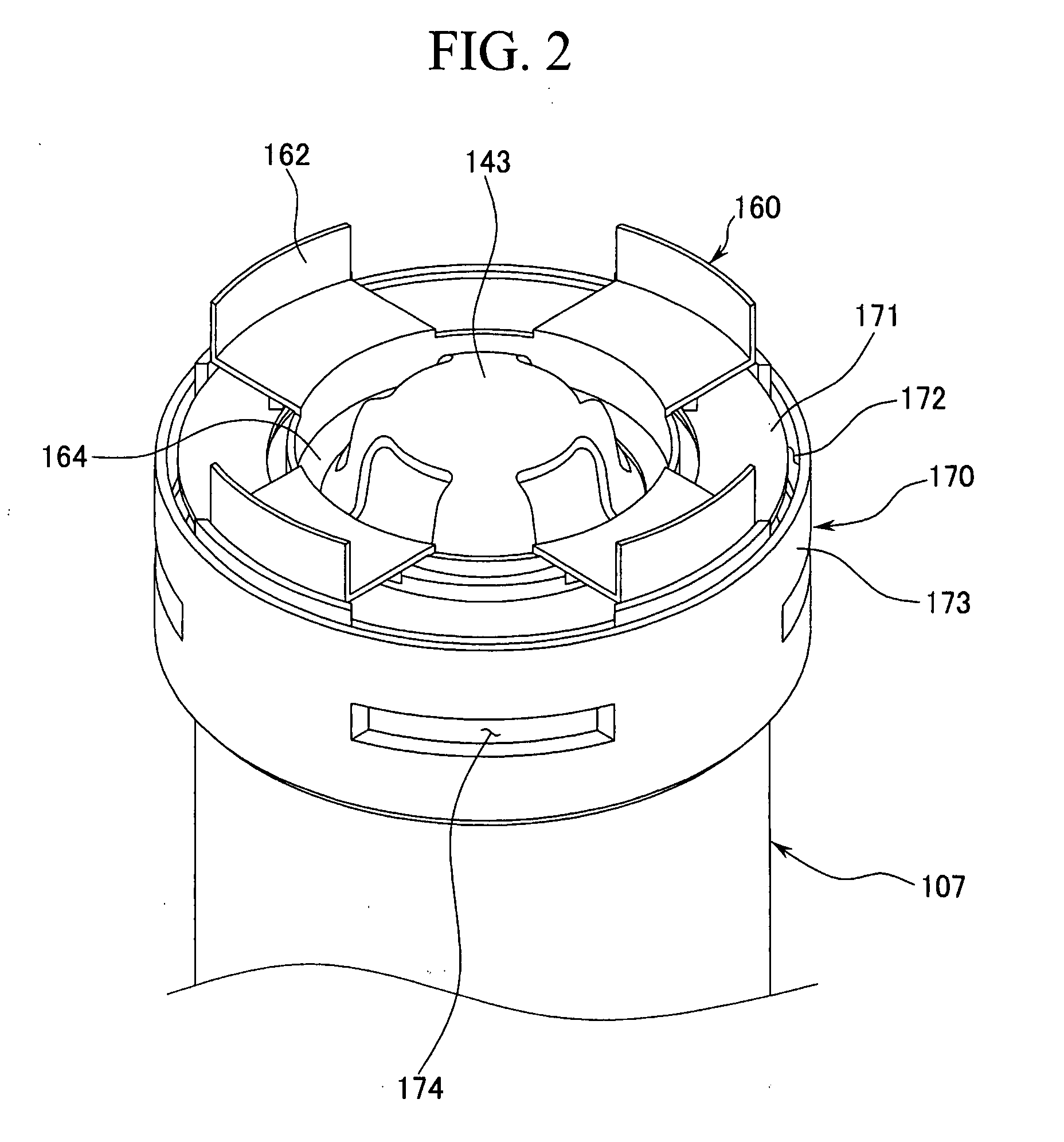
[0028]FIG. 1 is a partial cross-sectional exploded perspective view illustrating a battery module according to the first embodiment of the present invention. The battery module 100 according to the first embodiment of the invention includes first and second rechargeable batteries 107 and 105, respectively, constru...
PUM
 Abstract
Description
Claims
Application Information