Ventilator of a fuel-cell vehicle

a fuel-cell vehicle and ventilator technology, applied in the direction of cell components, electrochemical generators, cell component details, etc., can solve the problem of large suction device, achieve the effect of improving the cooling performance and improving the ventilating performan

Inactive Publication Date: 2012-09-18
HONDA MOTOR CO LTD
View PDF15 Cites 12 Cited by
  • Summary
  • Abstract
  • Description
  • Claims
  • Application Information

AI Technical Summary

Benefits of technology

[0005]Accordingly, an object of this invention is to provide a compact and high-efficient ventilator of the fuel-cell vehicle.
[0007]According to the above invention of the ventilator of the fuel-cell vehicle, the ventilating air flows strongly and smoothly as the ventilating air is supplied by the first ventilating device from the front side of the fuel-cell vehicle to the hydrogen-system unit area in the center of the fuel-cell vehicle, and flowed into the second ventilating device. Accordingly, the ventilator can ventilate efficiently the ambient gas in the hydrogen-system unit area as arranged in the center of front and rear direction of the fuel-cell vehicle. Further, the parts containing hydrogen are long arranged in the front and rear direction of vehicle body, such that the air caused by driving a vehicle (as referred hereinafter to as the driving air) is sucked from the front side of the parts containing hydrogen by the first ventilating device, the driving air (ventilating air) is sucked by the second ventilating device to supply it to the rear side of vehicle. Then, even in a case where the ambient gas existed in a position far from the suction port is sucked, the ambient gas can be effectively ventilated, as the ambient gas is flowed by the first ventilating device and the second ventilating device at a high speed from the front side to the rear side of vehicle body.
[0009]According to the above constitution, the hydrogen-system unit area is arranged inside the center tunnel of the fuel-cell vehicle. Further, the ventilating channel of the ventilating air as discharged from the first ventilating device, forms a throttle section toward the center tunnel to reduce in sectional area of the channel. Thus, it makes faster the flow velocity of the ventilating air penetrating the hydrogen-system unit area arranged downstream of the throttle section. Further, as the center tunnel is formed to cover like a tunnel and to be approximately pipe-shape so as to flow the ventilating air in the hydrogen-system unit area toward the rear side of vehicle body, the flow of the ambient gas containing hydrogen leaked in the hydrogen-system unit area is directed to the rear side of vehicle body. As a result, it can promote effectively the ventilation of the ambient gas in the hydrogen-system unit area.
[0013]According to the above constitution, the first ventilating device is a radiator fan making use of the driving air from the front side of the fuel-cell vehicle. Then, the driving air of the radiator fan for cooling down the cooling water of the fuel cell, auxiliary devices for power generation, and air conditioner can assist the ventilation thereof by the effective use as the ventilating air of the hydrogen-system unit area. Then, it improves the ventilating efficiency of the ventilator. As a result, the ventilating performance required for the first ventilating device can be obtained even in a small-size first ventilating device, and the miniaturization and power saving of the ventilator can be obtained.
[0017]According to the above constitution, the ventilating air flowing from the front side to the rear side of vehicle body can be flowed more rapidly, as the second ventilating device in the fuel cell vehicle is designed for cooling down the storage device of electricity by sucking the ambient gas in the space of the hydrogen-system unit area. Thus, the ventilating performance of the ventilator and the cooling performance can be improved.
[0018]The present invention can provide a compact and efficient ventilator of the fuel-cell vehicle.

Problems solved by technology

The conventional fuel-cell vehicle described in the above patent literature has a problem that a suction device becomes larger owing to the requirement of a suction device for a large amount of air in order to suck the ambient gas displaced far from the suction port, in a case where the parts containing hydrogen are long arranged in the front and rear direction of the vehicle.

Method used


Image

  • Ventilator of a fuel-cell vehicle
  • Ventilator of a fuel-cell vehicle
  • Ventilator of a fuel-cell vehicle

Examples


Embodiment Construction

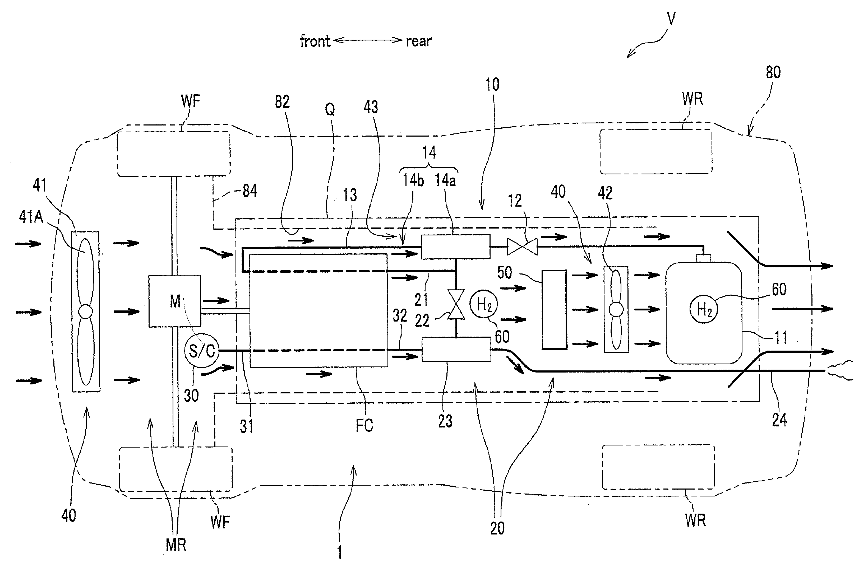
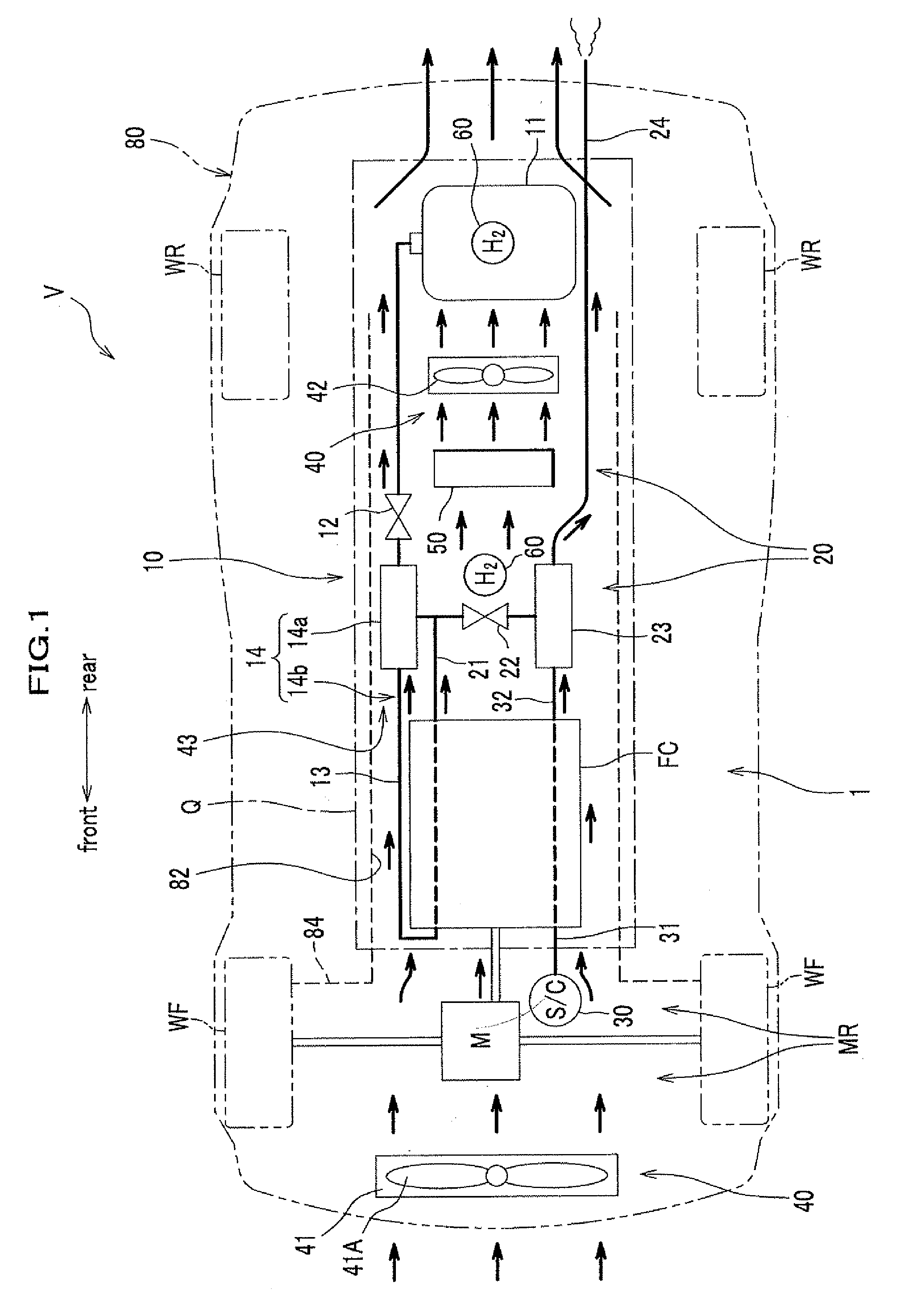
[0022]A ventilator of the fuel-cell vehicle relating to an embodiment of the present invention will be described as referred to FIG. 1 to FIG. 3.

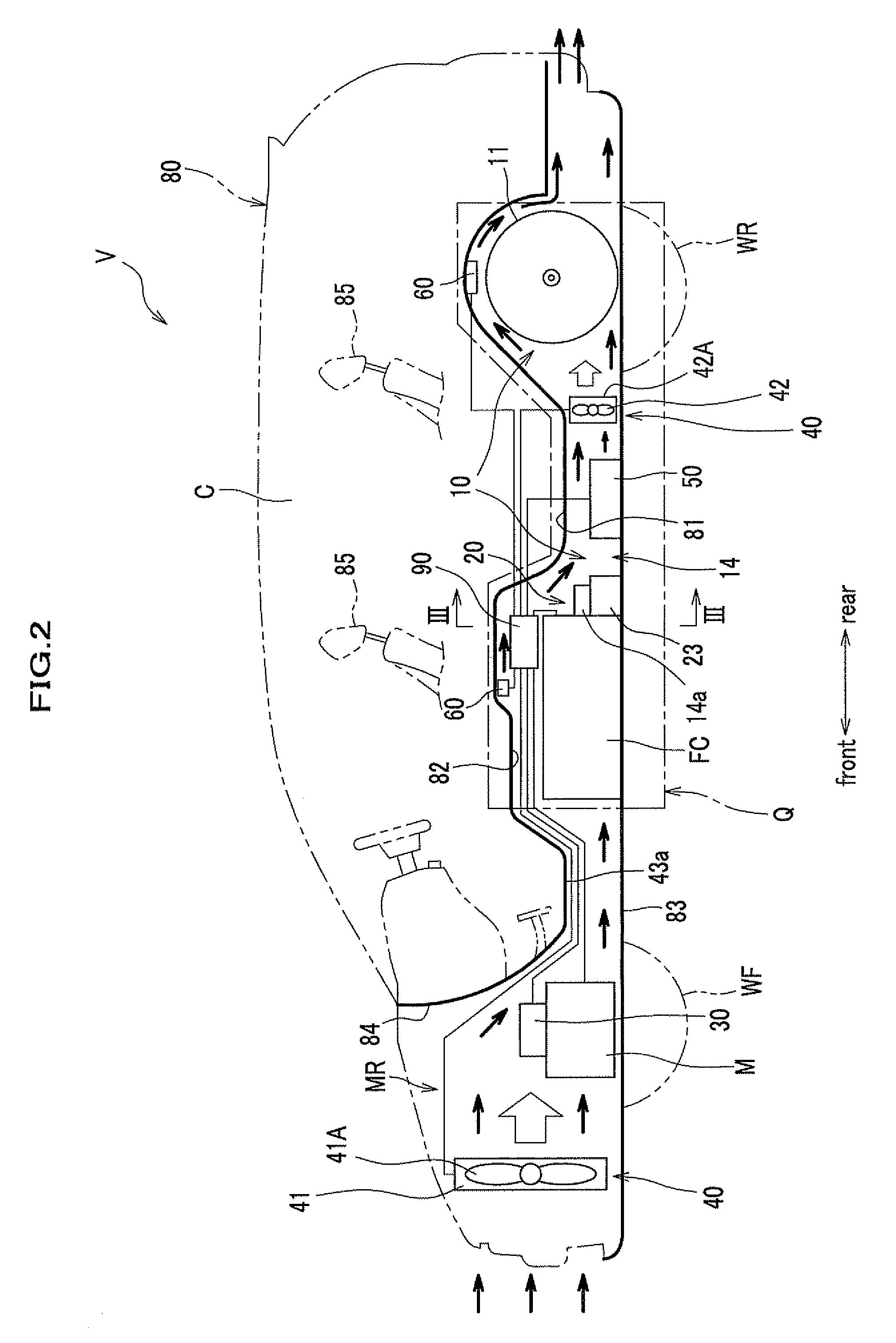
[0023]FIG. 1 is a schematic plan view showing a constitution of the ventilator of the fuel-cell vehicle relating to this embodiment. FIG. 2 is a schematic side view showing a constitution of the ventilator of the fuel-cell vehicle relating to the embodiment of the present invention. FIG. 3 is an enlarged cross-sectional view taken along a line III-III of FIG. 2. In addition, FIG. 1 to FIG. 3 show schematically and exaggeratedly the hydrogen-system unit area Q arranging a fuel cell FC and the like, and the ventilating channel 43.

Constitution of the Fuel-Cell Vehicles

[0024]As shown in FIG. 1, the fuel-cell vehicle V is an electric vehicle driven by rotating the driving motor M by means of the power generation of the fuel cell FC. The fuel-cell vehicle V boards the fuel-cell power generator 1, which is provided with the below-describing fuel c...


PUM

PropertyMeasurementUnit
velocityaaaaaaaaaa
areaaaaaaaaaaa
pressureaaaaaaaaaa

Abstract

The present invention relates to a ventilator of fuel-cell vehicles for ventilating hydrogen in the hydrogen-system unit area arranging a hydrogen circulating device in the fuel-cell vehicles boarding the fuel cell. The ventilator of fuel-cell vehicle includes a first ventilating device for taking ventilating air in from a front side of the fuel-cell vehicle to hydrogen-system unit area arranging the fuel cell, the hydrogen supply device, and the hydrogen exhaust device in the center of front and rear direction of the fuel-cell vehicle; and a second ventilating device for sucking the ventilating air taken in from the rear end of vehicle body of the fuel-cell vehicle to the hydrogen-system unit area.

Description

TECHNICAL FIELD[0001]The present invention relates to a ventilator of fuel-cell vehicles for ventilating hydrogen in the hydrogen-system unit area arranging a hydrogen circulating device in the fuel-cell vehicles boarding the fuel cell.BACKGROUND ART[0002]Conventionally, a fuel-cell power generator having the hydrogen-system unit area, which a fuel cell, a hydrogen supply device for supplying hydrogen to the fuel cell, and a hydrogen exhaust device for exhausting hydrogen from the fuel cell are arranged in the space between the floor panel and the under panel covering the bottom of vehicles, has been already known. For example, the patent literature (Japanese Unexamined Laid-open Publication No. 2007-80655) is given as an example. A suction device for sucking the ambient gas in the hydrogen-system unit area and a hydrogen detection device for detecting the hydrogen are provided in the fuel-cell vehicle.[0003]Thus, the above fuel-cell vehicle is able to detect the leak of hydrogen by...

Claims


Application Information

Patent Timeline
Patent Type & Authority Patents(United States)
IPC IPC(8): H01M8/04B60H1/24
CPCB60K11/06H01M8/04014H01M8/04089B60K2001/005Y02E60/50
Inventor MATSUMOTO, MITSUNORIMATSUTANI, MASAHIRO
Owner HONDA MOTOR CO LTD
Why Eureka
Try Eureka