Wind turbine generator system

a generator system and wind turbine technology, applied in the direction of electric generator control, machine/engine, cabinet/drawer/drawer, etc., can solve the problems of equipment damage, equipment damage, and equipment damage caused by an increase in the temperature of the equipment e, so as to improve the efficiency of air exhaust and reduce the effect of negative pressur

Active Publication Date: 2012-02-07
MITSUBISHI HEAVY IND LTD
View PDF31 Cites 11 Cited by
  • Summary
  • Abstract
  • Description
  • Claims
  • Application Information

AI Technical Summary

Benefits of technology

[0017]In such a wind turbine generator system, since the side air inlet is additionally provided in the side face of the nacelle at a position where a negative pressure is generated by air flowing outside the nacelle, the amount of outside air that is allowed to flow into the nacelle during operation is increased with the increase in the area of the air inlet, resulting in suppression of the temperature rise of the nacelle interior.
[0018]When the wind turbine generator system is not operated, the pressure of air flowing outside the nacelle becomes negative at the position where the side air inlet is provided. Therefore, the amount of outside air that flows into the nacelle from the additionally provided side air inlet can be minimized. Consequently, when the wind turbine generator system installed in a cool region is not operated, a temperature drop of the nacelle interior can be suppressed.
[0021]In this case, the rearward side air inlet is preferably positioned at an upper rearward portion of the side face of the nacelle. Thus, when the outside air temperature is high, the upper rearward portion, where the temperature is high, inside the nacelle can be efficiently ventilated by opening the rearward side air inlet.
[0022]The switching means is preferably provided with a front supporting swing member that is attached to the side air inlet and is openable outward at the rear side of the nacelle by using the nacelle front side as a fulcrum and a rear supporting swing member that is attached to the rearward side air inlet and is openable outward at the front side of the nacelle using the nacelle rear side as a fulcrum. Thus, the air exhaust efficiency can be increased by opening the side air inlet to increase the negative pressure, and the air intake efficiency can be increased by opening the rearward side air inlet to scoop the outside air flow for taking in the air.
[0023]Furthermore, the wind turbine generator system of the present invention is preferably provided with a front hood member that is attached to the outside of the side air inlet and that is closed at the nacelle front side and opened at the nacelle rear side and a rear hood member that is attached to the outside of the rearward side air inlet and that is opened at the nacelle front side and closed at the nacelle rear side. By doing so, with the side air inlet open, the air exhaust efficiency can be increased by the increase in negative pressure caused by the front hood member, and with the rearward side air inlet open, the air intake efficiency can be increased by the rear hood member scooping the outside air flow for taking in the air.
[0026]In the above-described wind turbine generator system of the present invention, the nacelle interior can be cooled irrespective of the outside air temperature in various installation environments even if the conditions, such as the outside air temperature, vary depending on the installation site and the season. That is, when the temperature of the nacelle interior is increased, the inside can be cooled by efficient ventilation, and when the temperature of the nacelle interior is decreased in, for example, a cool region, a temperature drop can be minimized with reduced ventilation.

Problems solved by technology

However, such ventilation cooling may not realize sufficient cooling performance depending on the installation environment of the wind turbine generator system 1 or the season.
In such an installation site, damage caused by an increase in the temperature of the equipment E is a problem.
Therefore, the surrounding temperature of the equipment E may decrease to a low temperature of −20° C. or less depending on the environment of the cool region, which may hinder the behavior of the equipment E when the operation is restarted, causing damage to the equipment E. To give a concrete example, a low temperature inside the nacelle 3 decreases the temperature of oils that are supplied to sliding portions of the equipment E for cooling and lubrication, resulting in an increase in viscosity.
Since such an increase in the viscosity of the oils increases the load when a pump is started, smooth starting of the pump is difficult, and, in addition, the pump or an engine may be damaged.

Method used


Image

  • Wind turbine generator system
  • Wind turbine generator system
  • Wind turbine generator system

Examples


first embodiment

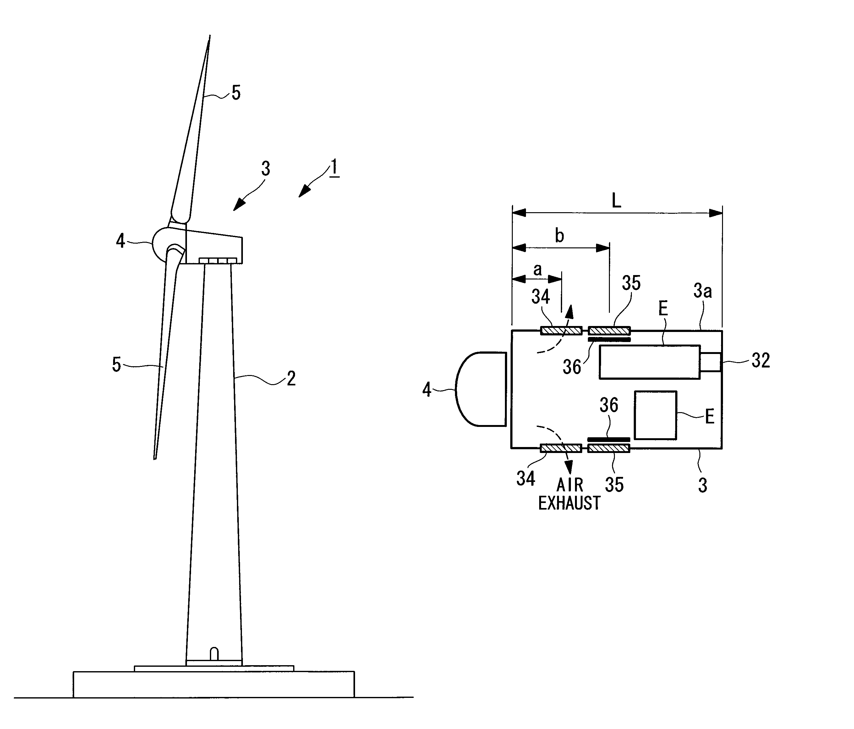
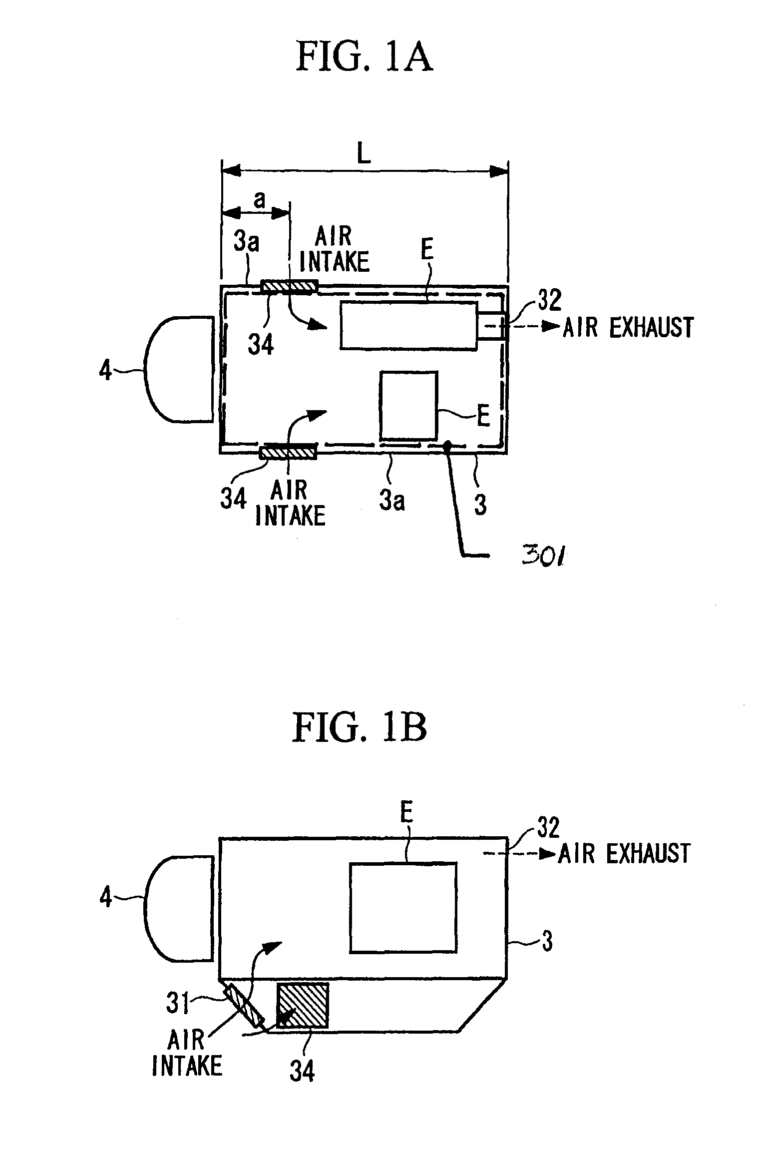
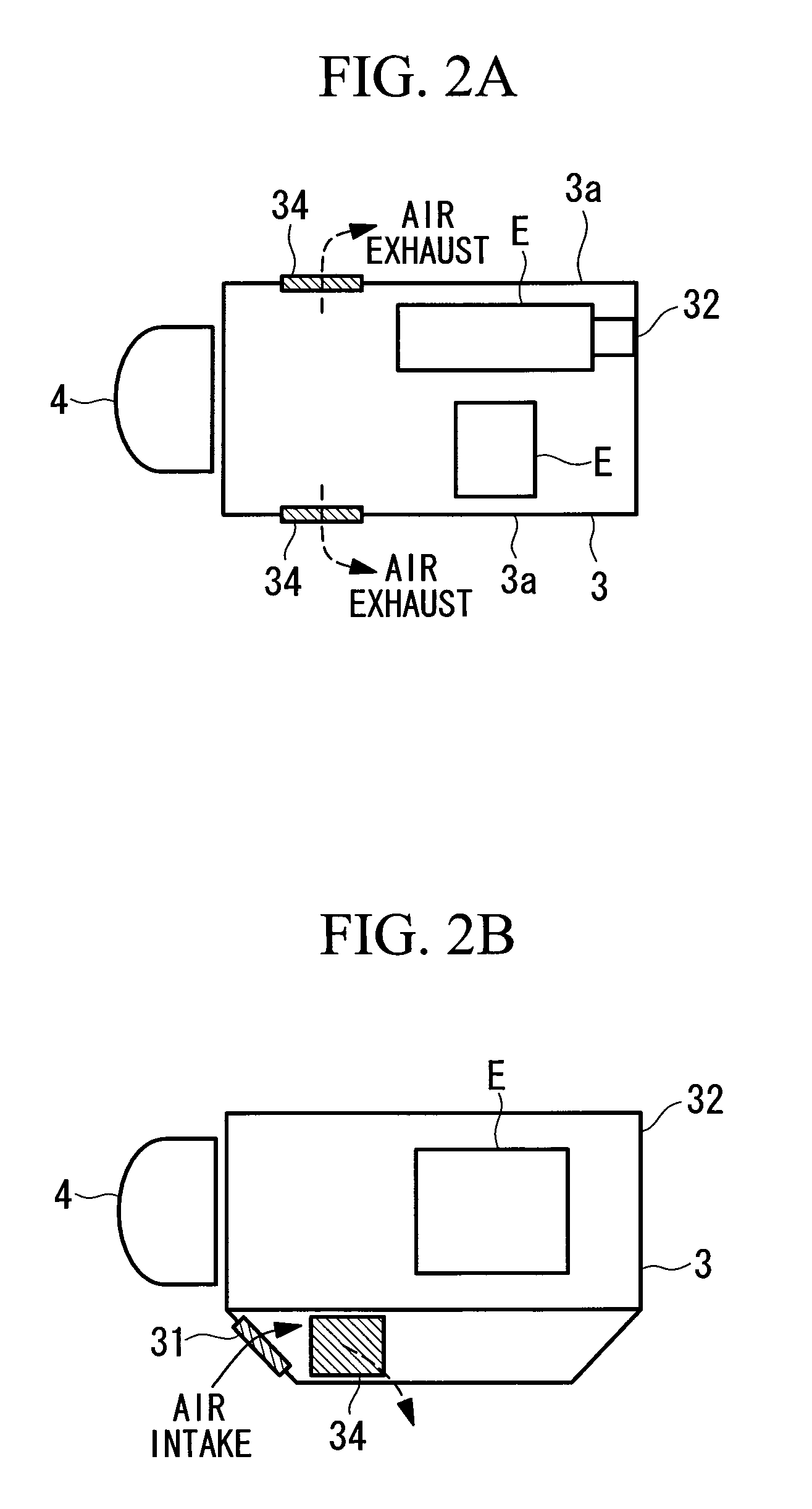
[0066]In such a wind turbine generator system 1, which will be described below, for example, as shown in FIGS. 1A, 1B, 2A, and 2B, side air inlets 34 are additionally provided in the side faces of the nacelle at positions where a negative pressure is generated by outside air flowing outside the nacelle 3. These side air inlets 34 are provided on both side faces of the nacelle 3.

[0067]The air inlet 31 is an opening provided at a lower portion of the front face of the nacelle 3 and is provided with a louver 40 described below. The lower portion of the front face in this case is a region lower than the position where the rotor head 4 rotates and is approximately near the bottom face of the nacelle 3.

[0068]The air outlet 32 is an opening for exhausting air and is disposed at an upper portion of the rear end face of the nacelle 3. This air outlet 32 is coupled to the outlet of a ventilation fan, which is disposed, for example, near the center of the upper end face of the nacelle 3, throu...

second embodiment

[0076]Next, the wind turbine generator system according to the present invention will be described with reference to FIGS. 4A, 4B, 5A, and 5B. Portions similar to those in the above-described embodiment are denoted by the same reference numerals and their detailed description is omitted.

[0077]In this embodiment, the rearward side air inlets 35 are additionally provided at positions that are located rearward of the nacelle with respect to the above-described side air inlets 34 and are located in non-negative pressure regions, where the negative pressure is eliminated, of the nacelle side faces 3a. These rearward side air inlets 35 are each provided with, for example, a slidable door member 36, as switching means for selecting an open or closed state of the side air inlets 34 and the rearward side air inlets 35.

[0078]The slidable door members 36 are configured so as to be capable of selecting an open or closed state where only the side air inlets 34 or the rearward side air inlets 35 ...


PUM


Abstract

Provided is a wind turbine generator system that can cool a nacelle interior by ventilation irrespective of the outside air temperature in various installation environments. In a wind turbine generator system in which equipment of drive and electricity generation mechanisms that are coupled to a rotor head provided with wind turbine blades is disposed inside a nacelle, and in which, by driving a ventilation fan provided in the nacelle, outside air introduced from an air inlet provided in a front face of the nacelle is exhausted outside the nacelle from an air outlet that communicates with a fan outlet, to perform ventilation cooling of the interior, a side air inlet is additionally provided in a side face of the nacelle at a position where a negative pressure is generated by air flowing outside the nacelle.

Description

CROSS-REFERENCE TO RELATED APPLICATIONS[0001]The present Application is based on International Application No. PCT / JP2008 / 069805, filed on Oct. 30, 2008, which in turn corresponds to Japanese Application No. 2008-193948 filed on Jul. 28, 2008, and priority is hereby claimed under 35 USC §119 based on these applications. Each of these applications are hereby incorporated by reference in their entirety into the present application.TECHNICAL FIELD[0002]The present invention relates to a wind turbine generator system using a windmill that converts natural wind power to rotary power for generating electricity.BACKGROUND ART[0003]Wind turbine generator systems generating electricity using wind power, which is natural energy, have been conventionally known. This type of wind turbine generator system includes, for example, like the wind turbine generator system 1 shown in FIG. 3, a rotor head 4 to which wind turbine blades 5 are attached, a main shaft coupled to the rotor head 4 so as to in...

Claims


Application Information

Patent Timeline
Patent Type & Authority Patents(United States)
IPC IPC(8): H05K5/00F03D9/00
CPCF03D11/00F05B2240/14Y02E10/726Y02E10/722F05B2260/20F03D80/60Y02E10/72F03D80/00
Inventor UCHINO, TAKASHISATO, SHINSUKEMATSUSHITA, TAKATOSHI
Owner MITSUBISHI HEAVY IND LTD
Why Eureka
Try Eureka