

Ultrasonic probe
a technology of ultrasonic probe and probe body, which is applied in the field of ultrasonic probe, can solve the problems of increasing the burden on the operator who manipulates the ultrasonic probe, the inability to expect a material to meet the two properties, and the weight increase in the entirety of the ultrasonic probe, so as to achieve the effect of suppressing the temperature rise exceeding
- Summary
- Abstract
- Description
- Claims
- Application Information
AI Technical Summary
Benefits of technology
Problems solved by technology
Method used
Image

Examples
first embodiment
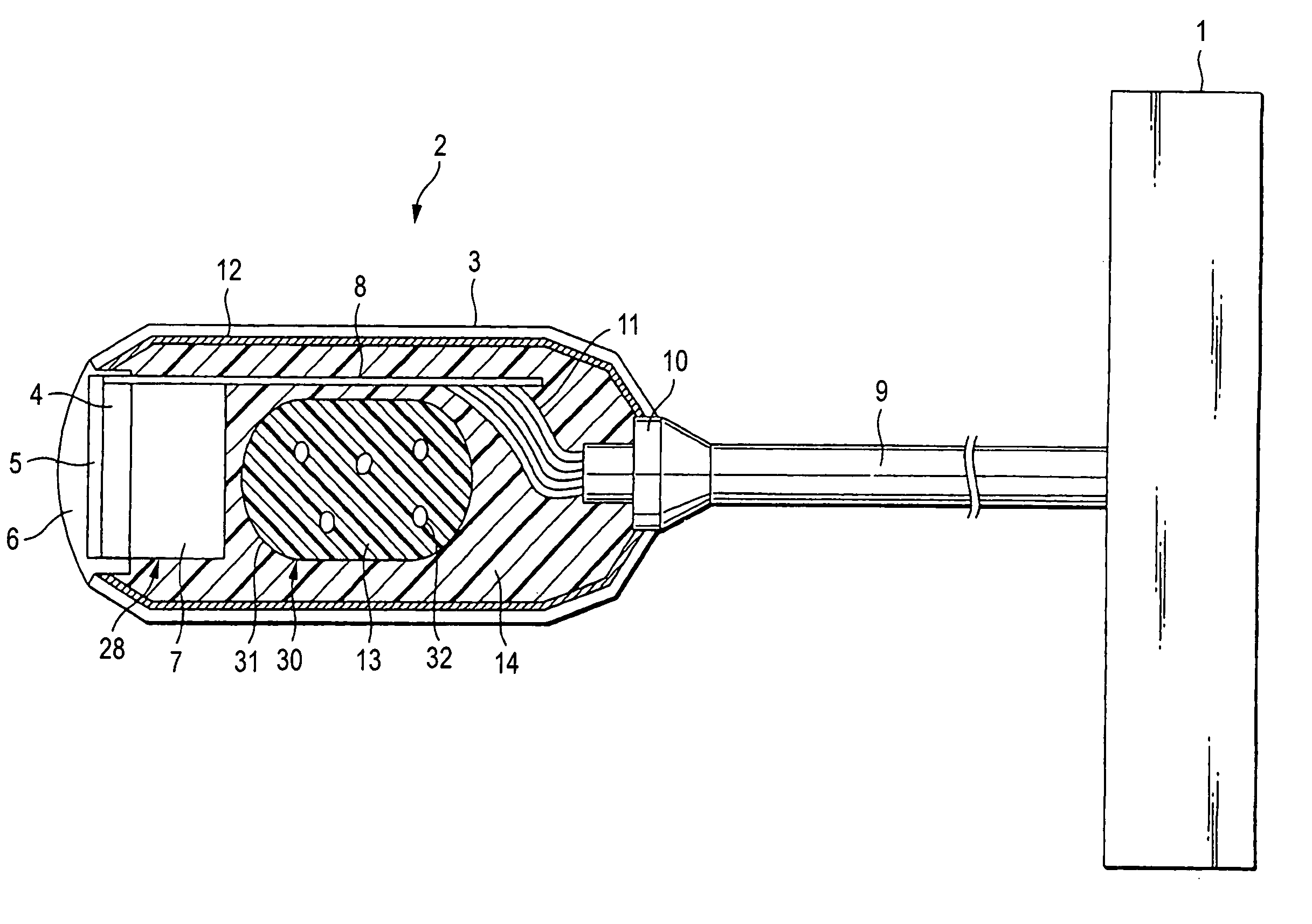
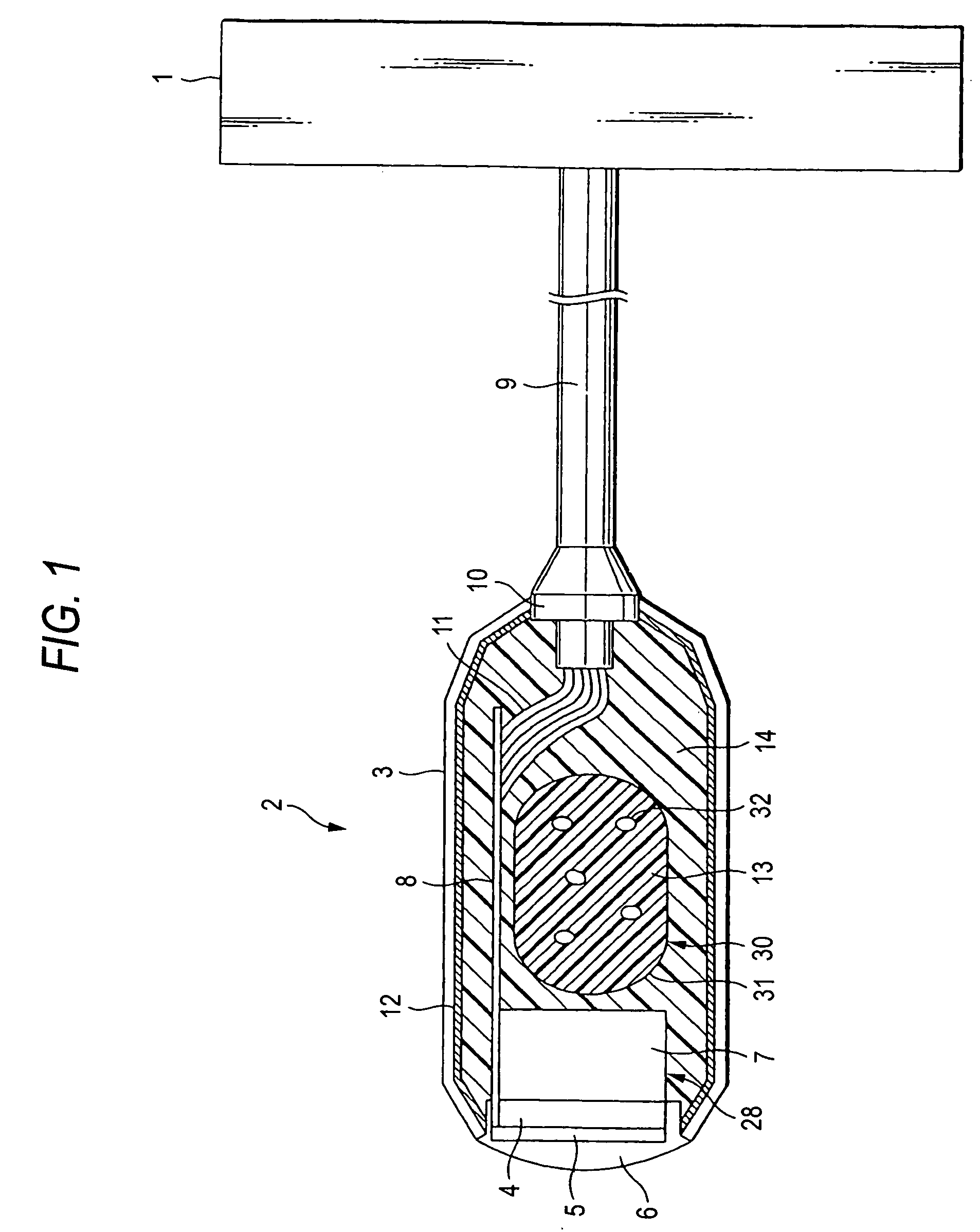
[0034] As shown in FIG. 1, a probe proper 2 has a probe housing 3. The probe housing 3 accommodates therein a transducer circuit 28, a flexible printed-wiring board 8 and a magnetic-shield member 2. The probe housing 3 has an interior surface over which is spread a magnetic-shield member 12 made by a metal film, metal mesh or metal case in order to shield the interior from a disturbance radio wave. A transducer unit 28 is made up with a transducer 4, an acoustic matching layer 5, an acoustic lens 6 and a backing material 107. The backing material 107 is arranged in back of the transducer 4. The acoustic matching layer 5 is arranged in front of the transducer 4. The acoustic matching layer 5 is provided to reduce the propagation loss of an ultrasonic wave. The acoustic lens 6 is arranged in front of the acoustic matching layer 5. The acoustic lens 6 is provided to converge an ultrasonic wave. The acoustic lens 6 is fit in an aperture formed in a tip of the probe housing 3. During exa...
second embodiment
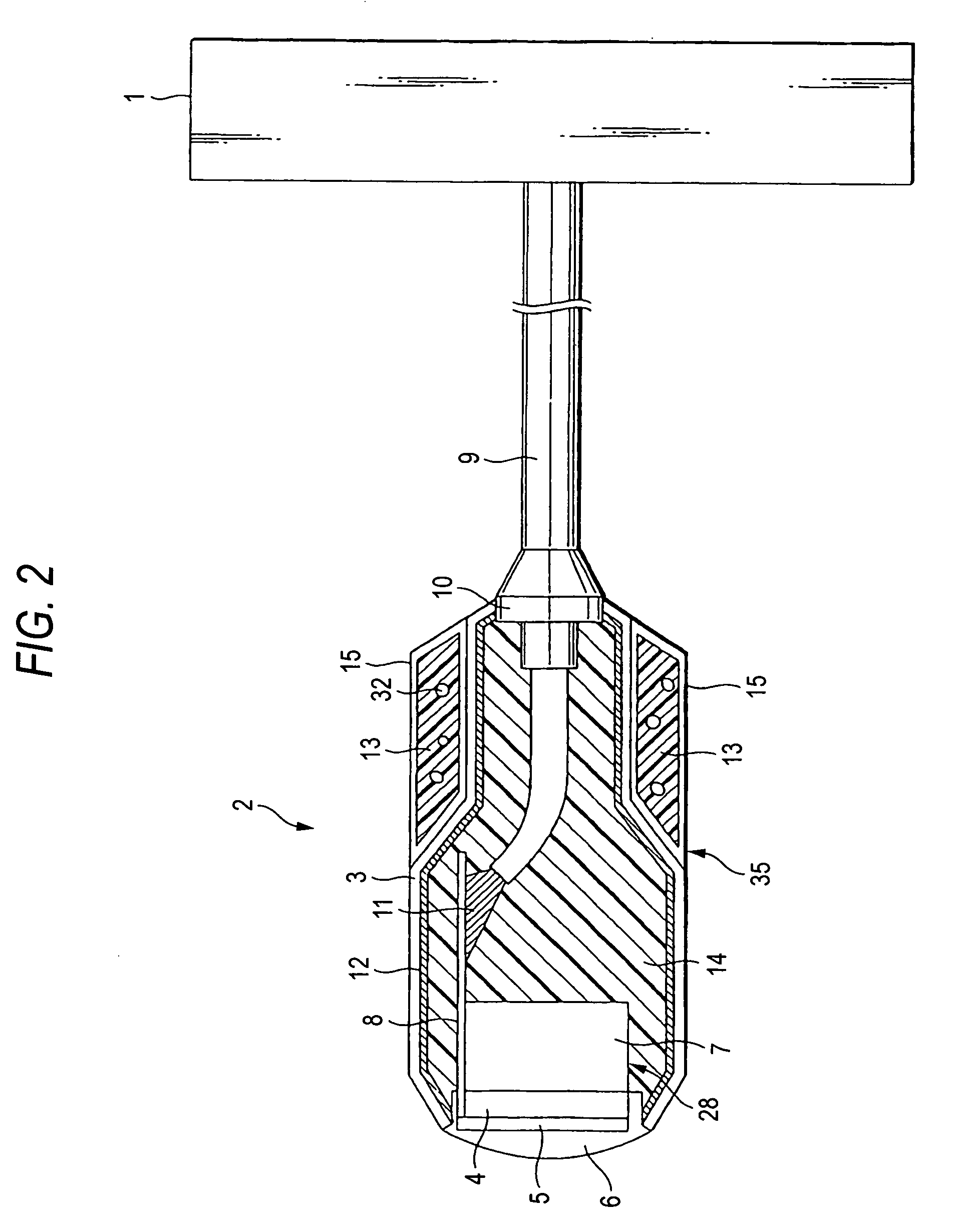
[0061] An ultrasonic probe in a second embodiment of the invention is explained in its structure while referring to FIG. 2. FIG. 2 is a sectional view showing an interior schematic structure of an ultrasonic probe according to a second embodiment of the invention.
[0062] In this embodiment, a phase change member 35 is made up with a phase change agent 13 mixed therein with gas bubbles 32, and a container 15 formed of a resin, a metal, graphite or a composite material thereof and containing the phase change agent 13, as shown in FIG. 2. The phase change member 35 is detachably provided external of the probe housing 3 and close to a cable 9 distant from a transducer unit 28. The phase change material uses a material similar to the first embodiment.
[0063] The container 15 is generally in a cylindrical form having an outer shape having a C-form in section partially cut away. The phase change member 35 is arranged to receive the cable 9 at an interior thereof through the cut-out of the ...
third embodiment
[0069] An ultrasonic probe in a third embodiment of the invention is explained in its structure while referring to FIGS. 3 and 4. FIGS. 3 and 4 are sectional views showing an interior schematic structure of an ultrasonic probe according to a second embodiment of the invention.
[0070] As shown in FIG. 3, a heat pipe (heat conductive member) 16, higher in heat conductivity than a filler agent 14, is provided within a probe proper 2 in this embodiment. The heat conductive member 16 has a generally Y-form. The heat conductive member 16 has one end in contact with or proximity to a backing material 7 bonded to a transducer 4, a heat source. The heat conductive member 16 extends toward the opposite to the transducer 4, i.e. toward a cable 9. The other end of the heat conductive member 16 is branched into a plurality of portions (two in the figure) of the heat conductive member 16 that are in contact with or proximity to side surfaces of a probe housing 3. The heat conductive member 16 is ...
PUM
| Property | Measurement | Unit |
|---|---|---|
| temperature | aaaaa | aaaaa |
| temperature | aaaaa | aaaaa |
| temperature | aaaaa | aaaaa |
Abstract
Description
Claims
Application Information