Power transmission coil

a technology of power transmission coil and transmission coil, which is applied in the direction of transformer/inductance coil/winding/connection, transformer/inductance details, etc., can solve the problems of difficult to suppress the heat generation as a whole, and the heat generation of the magnetic shield itself cannot be suppressed, so as to achieve the effect of improving the transmission efficiency

Inactive Publication Date: 2008-05-29
YONEZAWA ELECTRIC WIRE +1
View PDF11 Cites 44 Cited by
  • Summary
  • Abstract
  • Description
  • Claims
  • Application Information

AI Technical Summary

Benefits of technology

[0010]In the invention, the most part of the surface of the magnetic shield member on which the coil is disposed is covered by the coil, and hence the temperature rise as a whole of the coil can be suppressed and the transmission efficiency can be improved.

Problems solved by technology

This causes a problem that heat generation, malfunction, deterioration, and the like occur.
However, there still occur heat generation by the coil itself, and heat generation by the shield itself, so that it is difficult to suppress the heat generation as a whole.
The heat generation can be suppressed by improving the wire material and the like, but the heat generation by the magnetic shield itself cannot be suppressed.
As a result, heat generation is caused by a hysteresis loss and an eddy current loss.

Method used


Image

  • Power transmission coil
  • Power transmission coil
  • Power transmission coil

Examples


Embodiment Construction

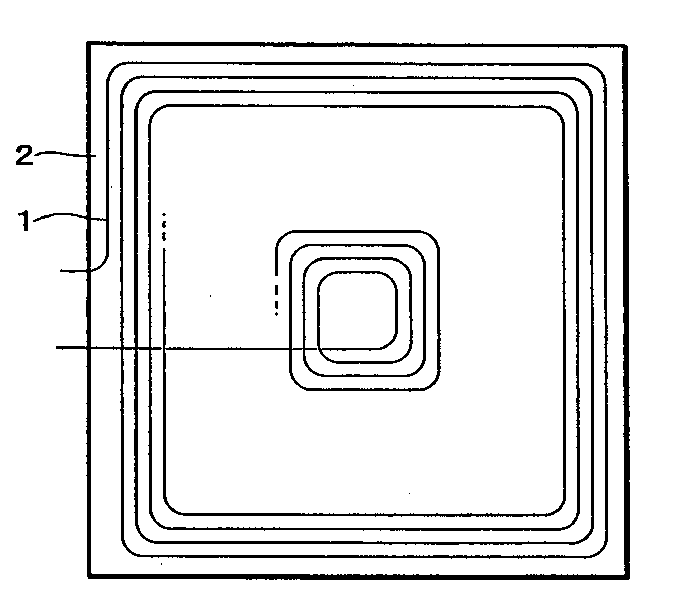
[0013]FIG. 1 is a schematic diagram showing an embodiment of the invention. In the embodiment, on a rear surface side of a coil (1) which is wound in a planar and substantially square manner, a square magnetic shield member (2) is disposed.

[0014]The coil (1) may be configured by a printed wiring on a laminated printed board, a single-core lead wire which is wound in a square manner, or a litz wire which is wound in a square manner.

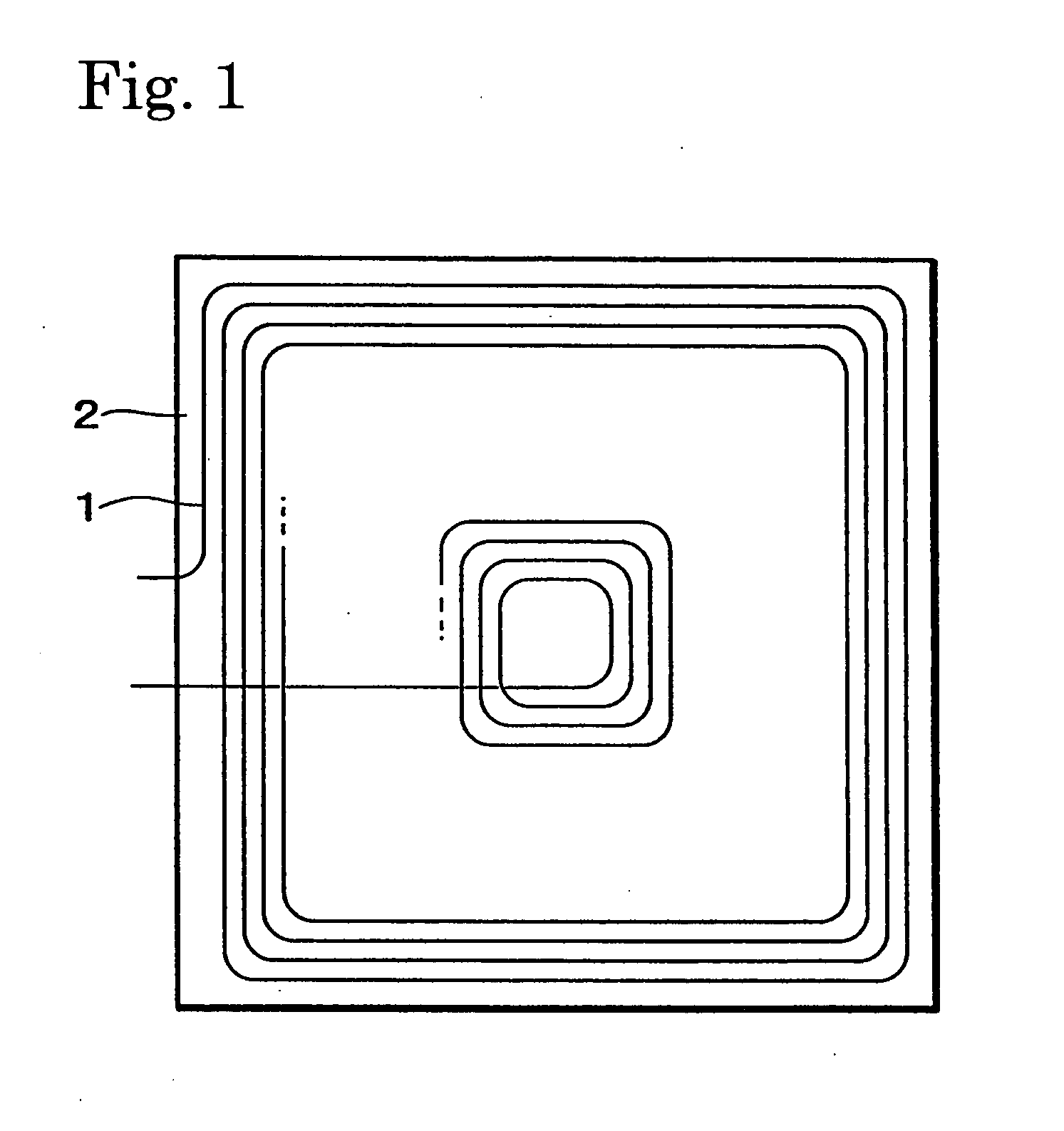
[0015]A power transmission coil having a conventional configuration shown in FIG. 2 in which a magnetic shield material of 35 mm square is disposed on the rear surface side of a circular coil wound in a circular manner with a diameter of 30 mm, and a power transmission coil having the configuration of the invention shown in FIG. 1 in which a magnetic shield material of 35 mm square is disposed on the rear surface side of a square coil wound in a square of 30 mm were left to stand until their temperature rises were saturated. In the case of the circular coi...


PUM

PropertyMeasurementUnit
diameteraaaaaaaaaa
temperatureaaaaaaaaaa

Abstract

A power transmission coil in which heat generation by a magnetic shield itself can be suppressed as far as possible is provided.A power transmission coil is configured by: a coil (1) wound in a plane; and a magnetic shield member (2) disposed on the rear surface of the coil (1). A most part, e.g. 65% or more, and preferably 70% or more of the area of the surface of the magnetic shield member (2) on which the coil is disposed is covered by the coil (1). In this case, the magnetic shield member (2) is formed in a rectangular shape, and the coil (1) is formed in a rectangular shape similar to the magnetic shield member (2).

Description

BACKGROUND OF THE INVENTION[0001]1. Field of the Invention[0002]The present invention relates to a power transmission coil which is to be used in a power system for a small portable electronic device such as a portable phone or a PDA, and particularly to a planar coil in which a coil is wound in a planar manner.[0003]2. Description of the Prior Art[0004]In general, a secondary battery is used as a power source in a power system for a small portable electronic device, and a planar coil is used in a charging circuit for the secondary battery (for example, see Patent Reference 1).[0005][Patent Reference 1] Japanese Patent Application Laying-Open No. 2002-25402[0006]In the prior art, on a precondition that such a coil is mounted, magnetic fluxes from a power transmission coil are absorbed by metal components such as a circuit board attached to the rear surface of the coil and the secondary battery. This causes a problem that heat generation, malfunction, deterioration, and the like occu...

Claims


Application Information

Patent Timeline
Patent Type & Authority Applications(United States)
IPC IPC(8): H01F27/36
CPCH01F5/003H01F17/0006H01F2027/2819H01F27/365H01F27/28H01F27/36
Inventor TAKAISHI, KONOMU
Owner YONEZAWA ELECTRIC WIRE
Why Eureka
Try Eureka