Alternating current light-emitting device and fabrication method thereof

a technology of alternating current and light-emitting device, which is applied in the manufacture of electrode systems, cold cathode manufacturing, and electric discharge tube/lamp manufacture, etc. it can solve the problems of waste of light-emitting area, unsatisfactory performance, and high cost, and achieve low starting forward bias, low cost, and high tolerance to reverse bias

Inactive Publication Date: 2008-05-08
EPISTAR CORP
View PDF8 Cites 90 Cited by
  • Summary
  • Abstract
  • Description
  • Claims
  • Application Information

AI Technical Summary

Benefits of technology

[0018]The method for fabricating the alternating current light-emitting device of the present invention comprises forming the rectifying unit on the rectifying element-dedicated member, wherein the rectifying element-dedicated member is formed on the substrate by epitaxy, deposition, diffusion, or implantation. Therefore, the rectifying elements are characterized by high tolerance to reverse bias and low starting forward bias, thereby reducing the number of the rectifying elements of the rectifying unit, providing more room for an increased number of microdie light-emitting elements, increasing unit area utilization, and enhancing light emission efficiency. Accordingly, the present invention overcomes a drawback of the prior art, that is, poor tolerance of conventional light-emitting microdies to reverse bias and a large number of light-emitting microdies required for rectification.

Problems solved by technology

In an AC-dominant living environment, conventional DC-driven LED chips can function well only in the presence of an external AC-to-DC converter circuit and a voltage drop element, thus resulting in high costs and unsatisfactory performance.
This problem calls for development of AC-operated LED chips.
This means a waste of light-emitting area, as only half of the microdies are operating at a forward bias at every single instant in an AC environment.
However, the design brought about another problem: LEDs have poor tolerance to a reverse bias, and thus rectification can only be achieved by LEDs when a large number of LEDs are used, which also results in a waste of microdie surface area.
Accordingly, the aforesaid drawbacks of the prior art call for immediate solution for directly fabricating on the surface of a LED die a rectifying element highly tolerant of reverse bias and characterized by low starting forward bias.

Method used


Image

  • Alternating current light-emitting device and fabrication method thereof
  • Alternating current light-emitting device and fabrication method thereof
  • Alternating current light-emitting device and fabrication method thereof

Examples


Embodiment Construction

[0024]The following specific embodiments are provided to illustrate the present invention. Persons skilled in the art can readily gain an insight into other advantages and features of the present invention based on the contents disclosed in this specification.

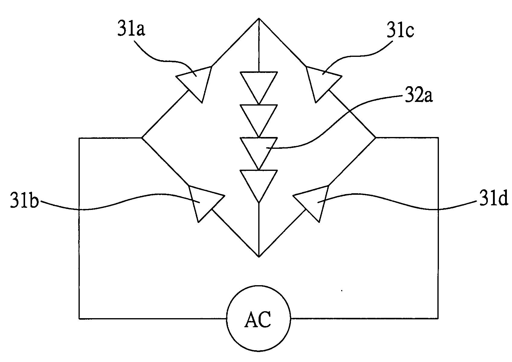
[0025]The present invention discloses an alternating current light-emitting device applicable to a substrate, for example, a chip. The alternating current light-emitting device is provided with a monochromatic or non-monochromatic light source by means of microdie light-emitting elements driven under an applied AC power rectified by, for example, a Wheatstone bridge circuit. The monochromatic or non-monochromatic light source is disposed on a light exit surface of the chip and is capable of full-time light emission. The alternating current is preferably the electricity supplied to the general public at voltages of 100V, 110V or 220V, and frequencies of 50 Hz or 60 Hz.

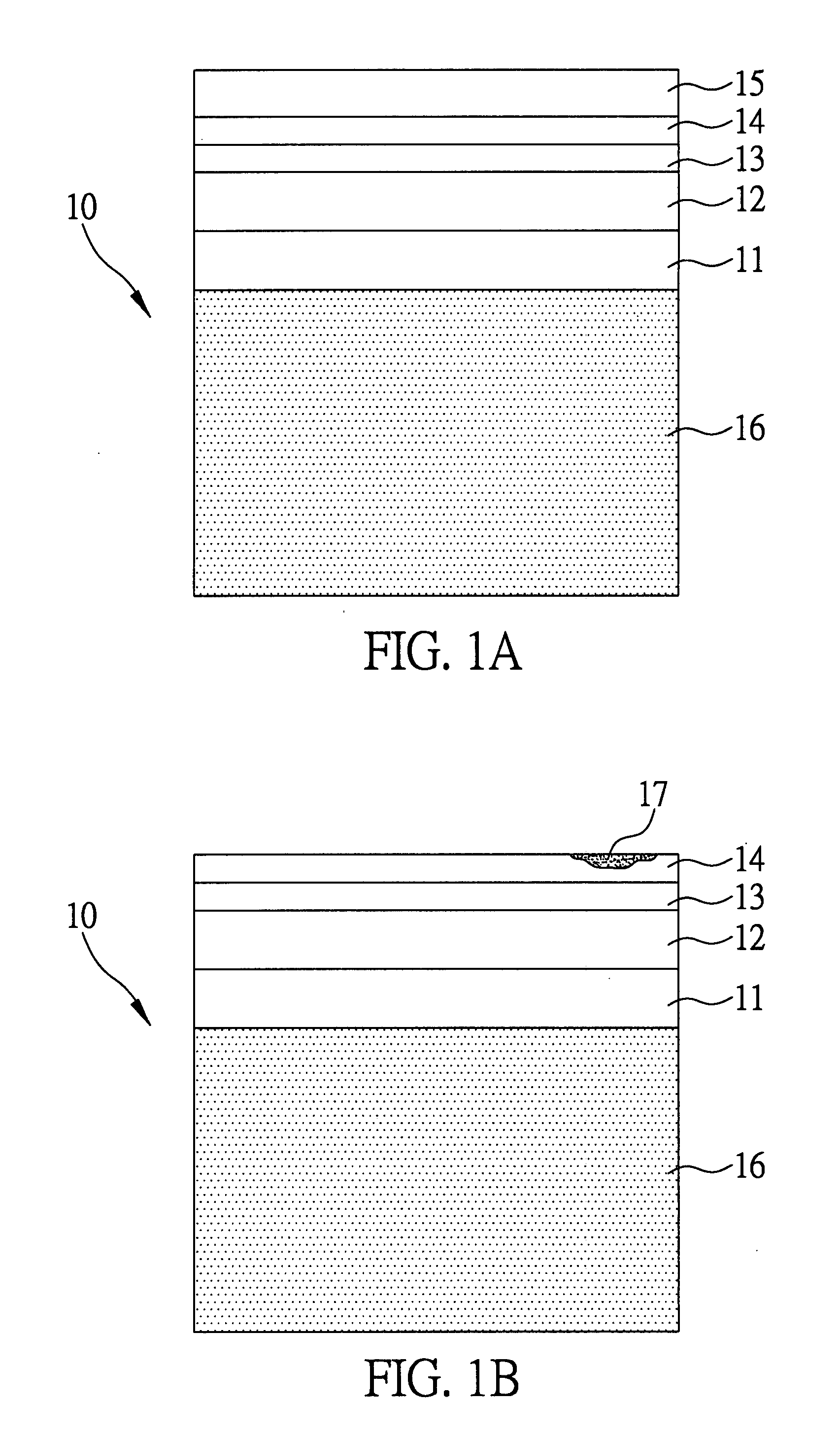
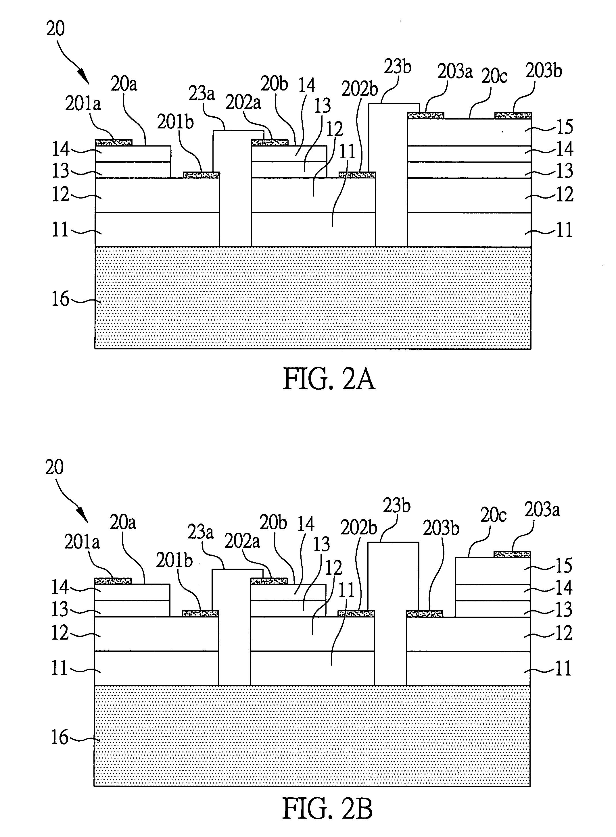
[0026]Referring to FIGS. 1A to 4B, which are schematic views ...


PUM


Abstract

An alternating current light-emitting device includes a substrate, a plurality of microdie light-emitting elements formed on the substrate, a rectifying element-dedicated member formed on a surface of a portion of microdie light-emitting elements, a rectifying unit formed on the rectifying element-dedicated member and provided with at least four rectifying elements forming a Wheatstone bridge circuit, and an electrically conductive structure electrically connecting the rectifying elements and the microdie light-emitting elements. With the rectifying unit being formed on the rectifying element-dedicated member, the rectifying elements are highly tolerant of reverse bias and feature low starting forward bias. Also, the present invention provides a method for fabricating an alternating current light-emitting device.

Description

BACKGROUND OF THE INVENTION[0001]1. Field of the Invention[0002]The present invention relates to light-emitting devices, and more particularly, to an alternating current light-emitting device and a fabrication method thereof.[0003]2. Description of the Prior Art[0004]With continual advances in optoelectronic technology, light emitting diodes (LED), a kind of light sources, are in wide use and of vital importance to optoelectronic industry. In an AC-dominant living environment, conventional DC-driven LED chips can function well only in the presence of an external AC-to-DC converter circuit and a voltage drop element, thus resulting in high costs and unsatisfactory performance. This problem calls for development of AC-operated LED chips. AC-operated LED chips (AC LED) have been put forth by manufacturers based in the United States, Japan, South Korea and China since 2005, indicating that AC LED is deemed a novel component of great potential.[0005]U.S. Pat. Nos. 6,547,249 and 6,957,899...

Claims


Application Information

Patent Timeline
Patent Type & Authority Applications(United States)
IPC IPC(8): H05B37/00H01J9/00
CPCH05B33/0803Y02B20/348H05B33/0821H05B33/0809H01L2224/48137H05B45/40Y02B20/30H05B45/30
Inventor YEN, HSI-HSUANYEH, WEN-YUNG
Owner EPISTAR CORP
Why Eureka
Try Eureka