Loudspeaker

a loudspeaker and amplifier technology, applied in the field of electrical audio signal processing systems and devices, can solve the problems of less than satisfactory sound produced by many loudspeakers in terms of quality and volume, and achieve the effect of increasing the peak-to-peak excursion of the forward cone, increasing the output of the loudspeaker, and increasing the volume limit of the loudspeaker

Inactive Publication Date: 2008-05-15
COBB JASON MYLES
View PDF7 Cites 0 Cited by
  • Summary
  • Abstract
  • Description
  • Claims
  • Application Information

AI Technical Summary

Benefits of technology

[0004]In light of the problems associated with the known loudspeakers, it is a principal object of the invention to provide a loudspeaker that features a pair of cones, with one positioned in front of the other, and a pair of supporting spiders that, together, maximize the peak-to-peak excursion of the forward cone without increasing either: 1) cone / spider diameters or 2) loudspeaker power requirements. Also, the rearward cone drives air like the forward cone, effectively increasing loudspeaker output. Thus, loudspeaker sound volume limits can be increased at minimal cost in space-restricted situations.
[0005]Another object of the invention is to provide a loudspeaker of compact size that can exceed the output, in terms of volume, frequency range, and quality, of a substantially larger loudspeaker of conventional construction.
[0006]It is an object of the invention to provide improved features and arrangements thereof in a loudspeaker for the purposes described that is lightweight in construction, inexpensive to manufacture, and dependable in use.

Problems solved by technology

Unfortunately, the small cabinets or other enclosures that are often expected to contain a loudspeaker place limits on the sizes of cones and spiders that can be used.
Thus, the sound produced by many loudspeakers is less than satisfactory in terms of its quality and volume.

Method used


Image

  • Loudspeaker
  • Loudspeaker

Examples


Embodiment Construction

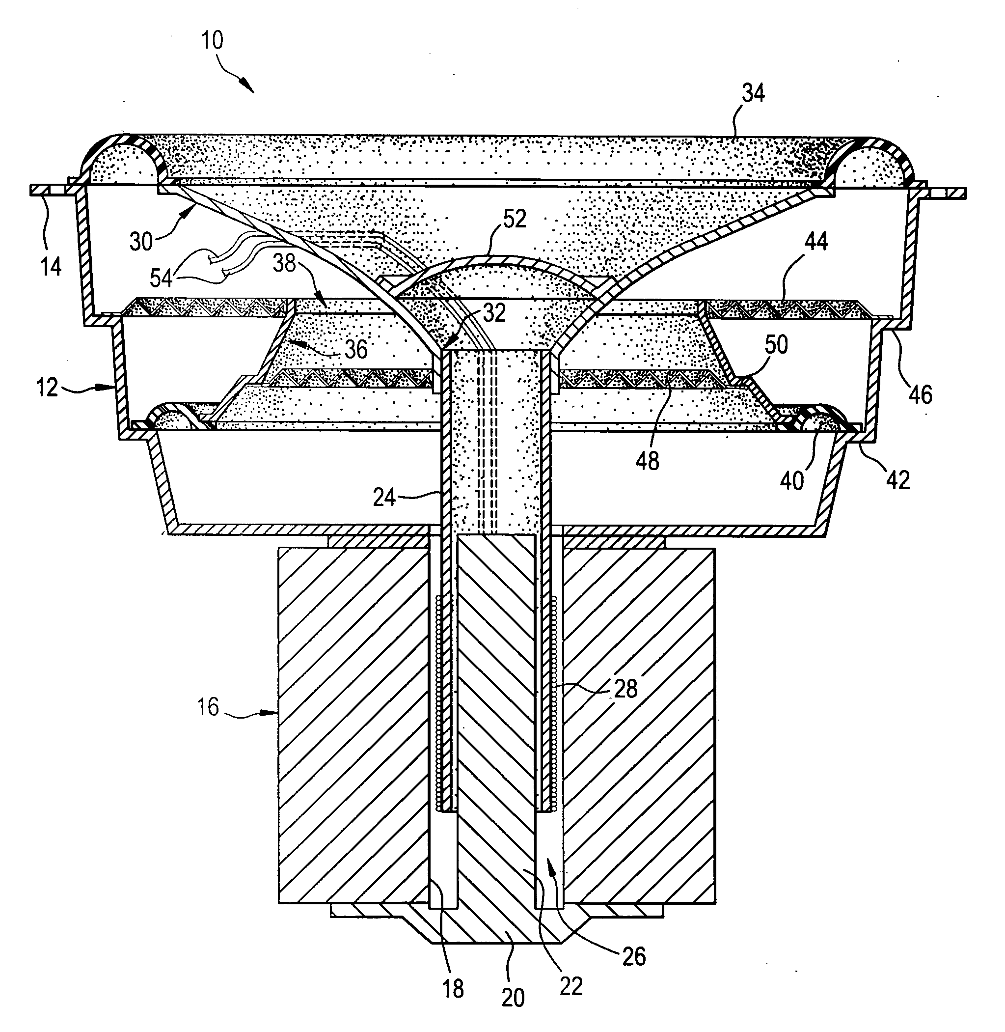
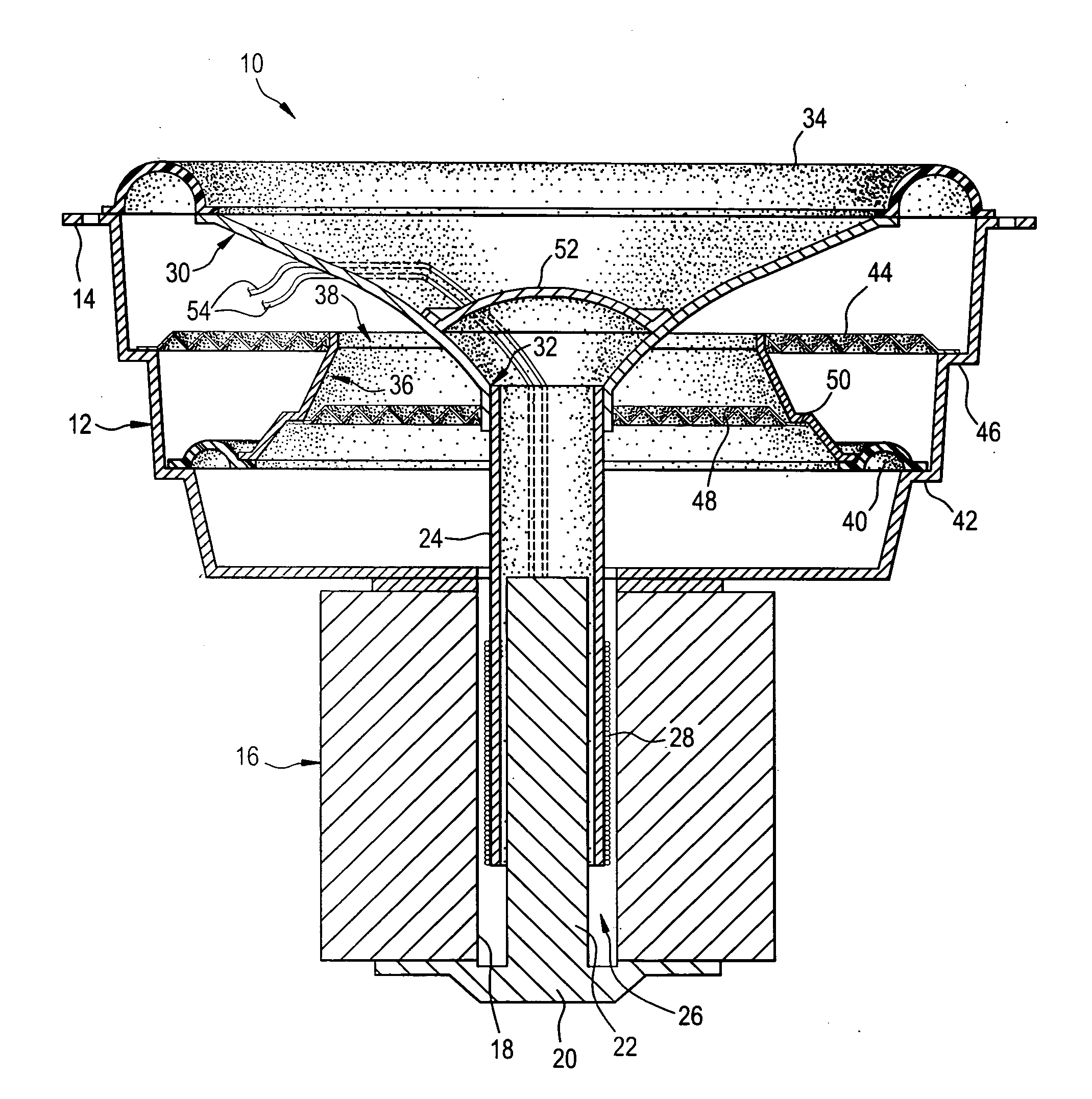
[0009]Referring now to the drawing, a loudspeaker in accordance with the present invention is shown at 10. Loudspeaker 10 includes a conical frame 12 having an outwardly extending, peripheral, mounting flange 14 at its wide, front end and, also, having a narrow, rear end to which is affixed a toroidal magnet 16 with a central passageway 18 that opens into frame 12. A cap 20 is affixed to the rear end of magnet 16 that closes passageway 18. A guide rod 22, integrally formed with cap 20, projects forwardly from cap 20 and through passageway 18. A tubular former 24 is slidably positioned upon rod 22 in the annular space 26 located in passageway 18 between rod 22 and magnet 16. A voice coil 28 is wound about, and is affixed to, former 24 yet is spaced away from magnet 26. The narrow, rear end of a forward cone 30 is affixed to former 28 and is provided with a central opening 32 that snugly receives the front end of former 28. The wide, front end of forward cone 30, however, is affixed, ...


PUM

PropertyMeasurementUnit
frequenciesaaaaaaaaaa
diameteraaaaaaaaaa
sizesaaaaaaaaaa

Abstract

A loudspeaker includes a frame and a toroidal magnet that is affixed to the rear of the frame. The toroidal magnet has a central passageway that opens into the frame. A cap is affixed to the rear of the magnet and closes the central passageway. A guide rod is affixed to the cap and projects forwardly from the cap into the central passageway. A tubular former is slidably positioned upon the guide rod. A voice coil is wound about, and is affixed to, the tubular former. A forward cone has a narrow, rear end that is affixed to the tubular former and a wide, front end that is affixed to the front of the frame. A rearward cone has a narrow, forward end with a central opening that loosely receives the rear end of the forward cone. The rearward cone also has a wide, rearward end that is affixed to the frame rearwardly of the front end of the forward cone. A forward spider is affixed to the forward end of the rearward cone and is affixed to the rear of the frame. A rearward spider is affixed to the rear end of the forward cone and is affixed to the rearward end of the rearward cone.

Description

FIELD OF THE INVENTION[0001]The present invention relates generally to electrical audio signal processing systems and devices and, more particularly, to electro-acoustic audio transducers having plural diaphragms.BACKGROUND OF THE INVENTION[0002]A conventional loudspeaker includes a diaphragm or cone that is vibrated to move air in a piston-like manner and generate audible sounds. Typically, a radially corrugated device called a “spider” is secured to the cone to maintain the cone's position before, during, and after, sound-producing vibrations are induced. A spider permits the cone to move forwardly and rearwardly from its resting position with the full range of motion being known as “peak-to-peak excursion.” As the peak-to-peak excursion of a loudspeaker cone increases, so does its ability to produce louder sounds, especially at lower frequencies.[0003]Peak-to-peak excursion of a loudspeaker cone is often enlarged by increasing the diameter of the spider attached to the cone and b...

Claims


Application Information

Patent Timeline
Patent Type & Authority Applications(United States)
IPC IPC(8): H04R1/02
CPCY10T29/49005H04R31/00
Inventor COBB, JASON MYLES
Owner COBB JASON MYLES
Why Eureka
Try Eureka