AI technical title is built by Patsnap AI team. It summarizes the technical point description of the patent document.
a technology of rotary wing vehicles and flying toys, which is applied in the field of self-stabilizing rotating flying toys, can solve the problems of price sensitive flying toys, and achieve the effects of improved yaw stabilization, great flying stability, and critical cost of materials
Inactive Publication Date: 2006-10-19
ZIMET NACHMAN +1
View PDF66 Cites 131 Cited by
Summary
Abstract
Description
Claims
Application Information
AI Technical Summary
This helps you quickly interpret patents by identifying the three key elements:
Problems solved by technology
Method used
Benefits of technology
Benefits of technology
[0009] The present invention provides an innovative rotary-wing apparatus that is aeronautically stable, easy to fly and control, very small in size, safe to fly and low cost to produce. In accordance with present invention a rotary-wing flying apparatus innovative design eliminates the need for gyros and motion sensors, expensive actuators and movable parts, rotor blades with changeable attacking angle, nor a tail rotor. Consequently making it possible to be produced in a very low cost, thus enabling implementations such as toys and other low cost applications. In addition it consists of innovative safety features for the operator and its surrounding making it possible to fly a rotary-wing platform of current invention even in doors.
[0010] Rotary-wing vehicle systems are well known and are being widely used for various mobile applications. Present invention diminishes at least some of the disadvantages associated with methods and solutions of very small helicopters that are designed for stability while maintaining minimal costs, a simple control, a high reliability, robustness and endurance and with no, or minimal need for tuning and adjustments.
[0011] In another embodiment of present invention, a coaxial counter rotating rotor drive is used, providing inherent aeronautical stability.
Problems solved by technology
Not like flying vehicles, flying toys are typically very prices sensitive.
Method used
Image
Click on the blue label to locate the original text in one second.
Reading with bidirectional positioning of images and text.
Examples
Embodiment Construction
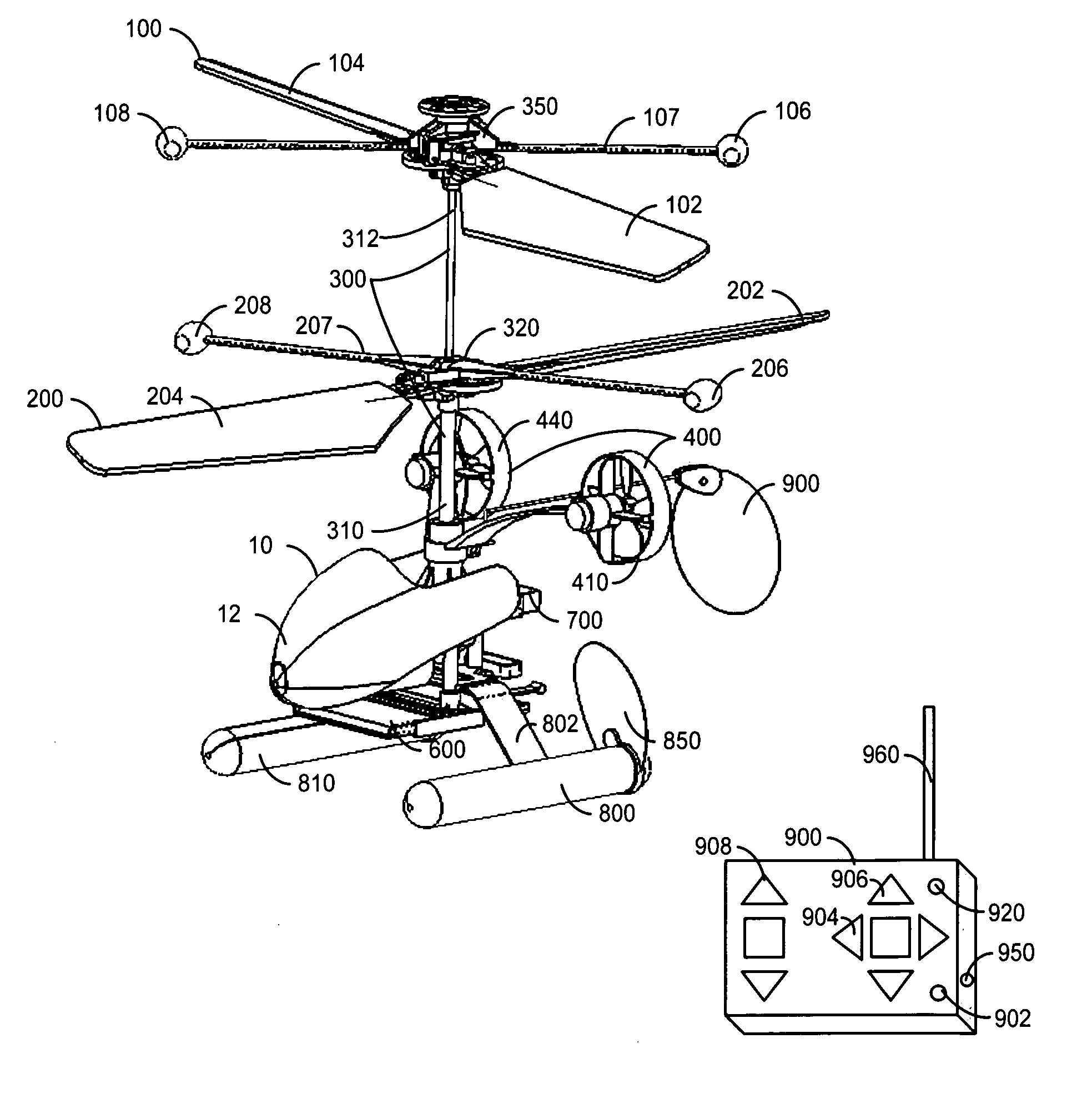
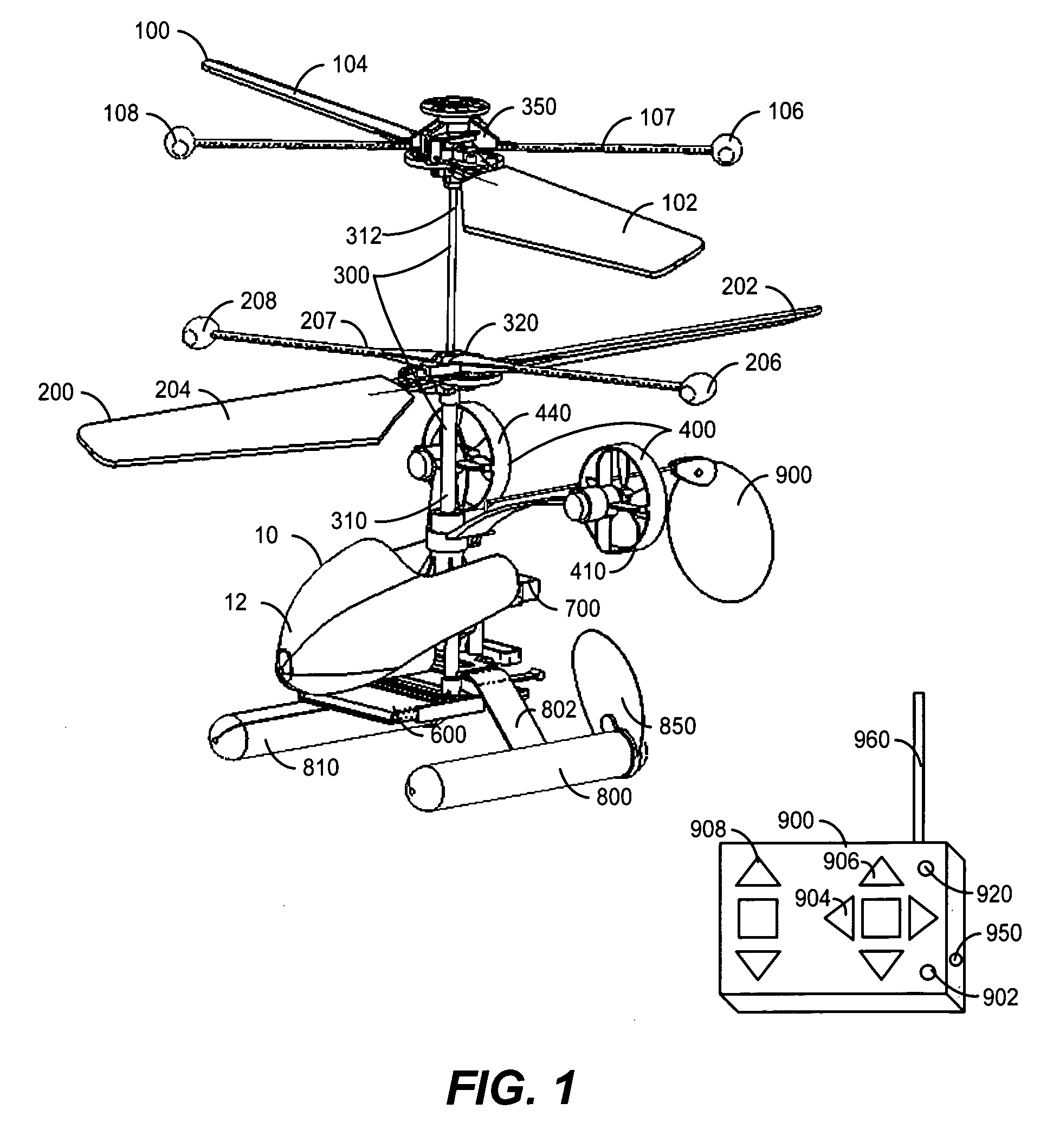
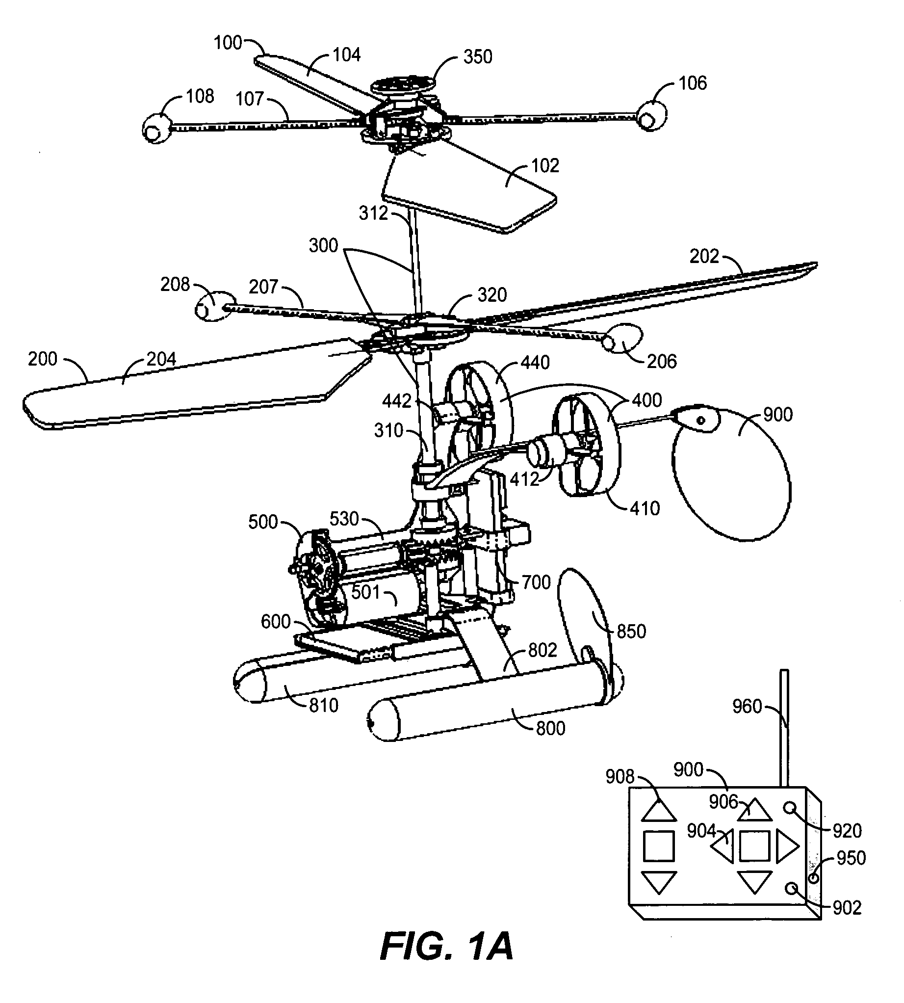
[0034] Reference is now made to FIGS. 1, 1A and 1B which are simplified pictorial diagrams illustrating one preferred embodiment of the present invention, a rotary-wing flying apparatus operating in plurality of applications. The illustrated embodiment of FIG. 1, 1A and 1B are presented in the context of flying toys, it is understood that this embodiment of the invention is not limited to toys and is equally applicable to other suitable types of small flying objects where cost, stability and ease of use are of importance.
[0035]FIG. 1 illustrates a front isometric view of a micro Rotary-wing apparatus 10 of a preferred embodiment of current invention.
[0036] A micro Rotary-wing apparatus 10 consists of two sets of counter rotating blades, a lower rotor blades system 200 and the upper rotor blades system 100.
[0037] A main coaxial drive shaft 300 provides a rotating power to said two sets of counter rotating blades 100, 200. A main coaxial drive shaft 300 consists of two parts: an ou...
PUM
Abstract
A rotary-wing apparatus that is aeronautically stable, easy to fly with a multidimensional control, small size, and safe to fly and low cost to produce. The rotary-wing apparatus includes a coaxial counter rotating rotor drive providing lifting power with an inherent aeronautical stability; Auxiliary propellers that face the direction of flight and are located on opposite sides of said coaxial Rotary-wing apparatus and enable flying forwards, backwards and perform yawing; A rotary-wing coaxial helicopter toy that is remotely controlled and safe to fly in doors and out doors, while performing exciting maneuvers even by untrained kids
Description
[0001] This application is based on provisional application No. U.S. 60 / 624,941 filed on Nov. 5, 2004FIELD OF THE INVENTION [0002] The present invention relates to flying apparatuses generally and more specifically to self-stabilizing rotating flying toys. BACKGROUND OF THE INVENTION [0003] The following U.S. Patents are believed to represent the current state of the art: 5,252,100October 1993Osawa, et al.446 / 44D465,196November 2002DammarD12 / 3286,899,586May 2005Davis446 / 376,843,699January 2005Davis446 / 376,688,936February 2004Davis446 / 375,971,320October 1999Jermyn, et al.244 / 17.256,568,980May 2003Barthold446 / 366,450,446September 2002Holben244 / 34A6,616,094September 2003Illingworth244 / 12.1D503,198March 2005Rehkemper, et al.D21 / 4426,802,693October 2004Reinfeld, et al.416 / 16,824,094November 2004Richard244 / 116,568,634May 2003Smith244 / 726,086,016January 2000Meek244 / 17.115,297,759March 1994Tilbor, et al.244 / 17.116,811,460November 2004Tilbor, et al.446 / 34[0004] The passion of flying has acc...
Claims
Application Information
Patent Timeline
Application Date:The date an application was filed.
Publication Date:The date a patent or application was officially published.
First Publication Date:The earliest publication date of a patent with the same application number.
Issue Date:Publication date of the patent grant document.
PCT Entry Date:The Entry date of PCT National Phase.
Estimated Expiry Date:The statutory expiry date of a patent right according to the Patent Law, and it is the longest term of protection that the patent right can achieve without the termination of the patent right due to other reasons(Term extension factor has been taken into account ).
Invalid Date:Actual expiry date is based on effective date or publication date of legal transaction data of invalid patent.
Patent Type & AuthorityApplications(United States)

