Yaw Aerodynamically Stabilized Lifting Body Vehicle

A technology for an aircraft and a lifting body, which is applied in the field of yaw aerodynamic stabilization type lifting body aircraft, can solve the problems of increasing the difficulty of the aircraft structure and thermal protection design, and rapidly increasing resistance, so as to improve the yaw stability and avoid structural problems. Effect

Active Publication Date: 2016-08-24
CHINA ACAD OF AEROSPACE AERODYNAMICS
View PDF5 Cites 0 Cited by
  • Summary
  • Abstract
  • Description
  • Claims
  • Application Information

AI Technical Summary

Problems solved by technology

However, for the lifting body that mainly flies in the hypersonic state, the exposed aerodynamic rudder surface will bring some insurmountable disadvantages: 1. In the hypersonic flight state, the wave resistance generated by the aerodynamic rudder surface will increase the resistance rapidly; 2. The thin aerodynamic rudder surface increases the difficulty of aircraft structure and thermal protection design; 3. The aerodynamic rudder surface faces serious aeroelasticity / aerodynamic thermoelasticity problems in the hypersonic flight state

Method used


Image

  • Yaw Aerodynamically Stabilized Lifting Body Vehicle
  • Yaw Aerodynamically Stabilized Lifting Body Vehicle
  • Yaw Aerodynamically Stabilized Lifting Body Vehicle

Examples


Embodiment

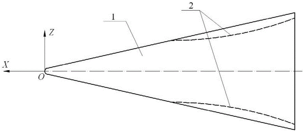
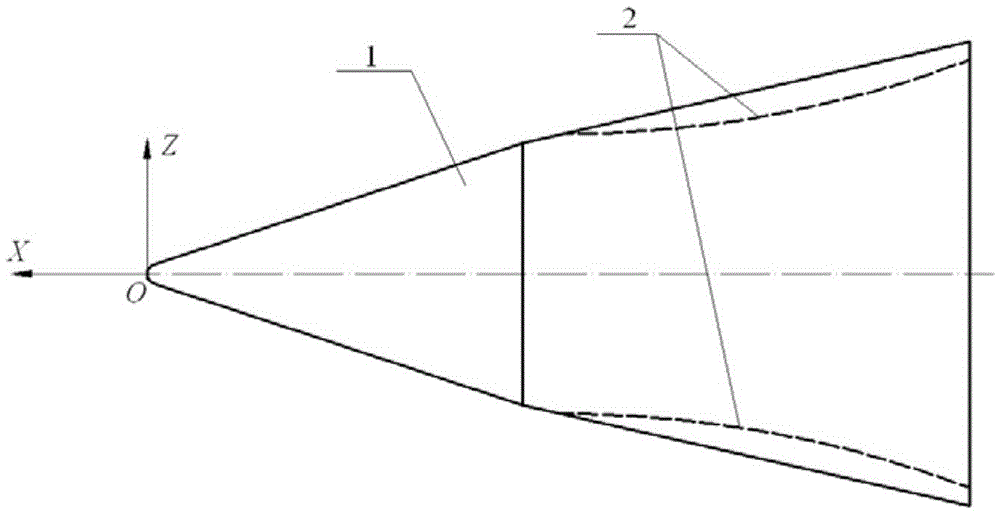
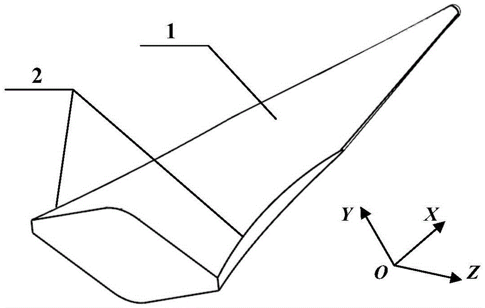
[0023] Such as Figure 1 ~ Figure 4 As shown, the present invention provides a yaw aerodynamically stabilized lifting body aircraft, which includes a body 1 and a lateral section 2 . Such as Figure 1 ~ Figure 2 As shown, the body can be a single cone or multiple cones. Such as Figure 3 ~ Figure 4 As shown, the cross-sectional shape of the body can be a rhombus or an ellipse. Simultaneously, other aerodynamic rudder surfaces can be provided on the body. Carry out cutting to the both sides of body 1 to form such as Figure 1 ~ Figure 4 Lateral cuts 2 are shown to create an aerodynamic stabilization zone. The lateral section 2 of the present invention is located on both sides of the rear part of the body 1 of the lifting body aircraft, and is perpendicular to the XOZ plane of the aircraft. Such as image 3 As shown, OZ represents the width direction of the aircraft, OX represents the length direction of the aircraft, and OY represents the height direction of the aircraft...

example 1

[0026] Example 1: The total length of the lifting body model is 4000mm, Figure 5 A 3D model of the original shape is given, Figure 6 The dimensions of the lifting body vehicle are given: the radius of the bottom of the head is 50 mm, the radius of the upper and lower roundings is 390 mm, the width of the bottom is 1900 mm and the radius of the bottom side edges is 25 mm. The method of the invention is used to cut the two side surfaces of the rear body of the original shape to form a yaw aerodynamic stabilization shape. The specific cutting adopts radius R S For an arc of 5700mm, start cutting the curved surface at a distance of 2050mm from the head. The curve configuration of the cutting surface on the XOZ plane is that the tangent of the cutting start point on the curve is parallel to the central axis. At the same time, in order to ensure the compression effect of the rear body, the bottom of the model is cut in a small range, see Figure 7 .

[0027] The specific gove...


PUM


Abstract

The invention discloses a yawing pneumatic control augmentation type lift-body vehicle which comprises a body and a lateral tangent plane, wherein the lateral tangent plane is positioned on two sides in the rear of the body; the lateral tangent plane is a curved surface; as the curved surface is close to the rear of the body, the slope of the curved surface is gradually increased relative to a central axis of the body; the lateral tangent plane is perpendicular to an XOZ plane of the vehicle. An expansion-compression process allowing the rear body to laterally flow is constructed only through the lateral tangent plane based on a pneumatic principle, the yawing stability of the vehicle can be effectively improved, and the problems such as structure, thermal protection and pneumatic elasticity / pneumatic thermoelasticity brought by the process of mounting a heading stability plane are solved.

Description

technical field [0001] The invention relates to a lifting body aircraft, in particular to a yaw aerodynamic stabilization type lifting body aircraft. Background technique [0002] Since the lifting body aircraft mainly relies on the fuselage to generate the lift required for flight, the lifting body has a high volume characteristic; at the same time, due to the simple structure and the large bluntness of the fuselage, the difficulty of thermal protection of the aircraft and the thermal protection system are greatly reduced. Additional mass. Therefore, the lifting body vehicle has gradually become an important choice for the layout of space reentry vehicles. [0003] In terms of stability, the stability of the yaw channel of the lifting body aircraft is relatively weak, and with the increase of the Mach number and the angle of attack, the yaw stability decreases significantly, so ensuring sufficient yaw stability is the key to the aerodynamic design of the lifting body layou...

Claims


Application Information

Patent Timeline
Patent Type & Authority Patents(China)
IPC IPC(8): B64C5/00B64C1/00
Inventor 赵俊波张瑞民董金刚沈清
Owner CHINA ACAD OF AEROSPACE AERODYNAMICS
Why Eureka
Try Eureka