Support roller for drying grate

A technology for grate machines and rollers, which is applied in the direction of rollers, conveyors, conveyor objects, etc., can solve the problems of increased wear and energy consumption, and achieve the goals of reducing driving energy consumption, reducing driving energy consumption, and reducing wear Effect

Inactive Publication Date: 2009-07-29
SHANDONG PROVINCE METALLURGICAL ENG CO LTD
View PDF0 Cites 0 Cited by
  • Summary
  • Abstract
  • Description
  • Claims
  • Application Information

AI Technical Summary

Problems solved by technology

[0003] The purpose of the present invention is to provide a kind of chain grate idler roller, to overcome the grate bed that existing chain grate idler roller exists and the relative sliding of smooth idler surface, thus produce additional resistance, increase wear and tear and Disadvantages of energy consumption

Method used


Image

  • Support roller for drying grate
  • Support roller for drying grate
  • Support roller for drying grate

Examples


Embodiment 1

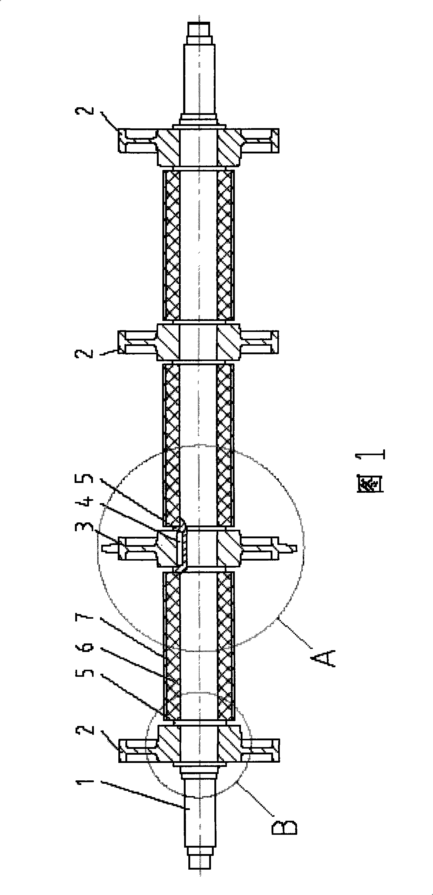
[0021] It should be noted that the idler rollers of the grate machine have various forms. In terms of the number of sprockets and smooth rollers alone, there is a big difference. For example, for a grate bed with 6 rows of chains, the sum of smooth rollers and sprockets on the rollers is 6; for a grate bed with 7 rows of chains, the sum of smooth rollers and sprockets on the rollers is 7, etc. In this embodiment, only the idler roller with four smooth idlers and sprockets on the idler roller will be described.

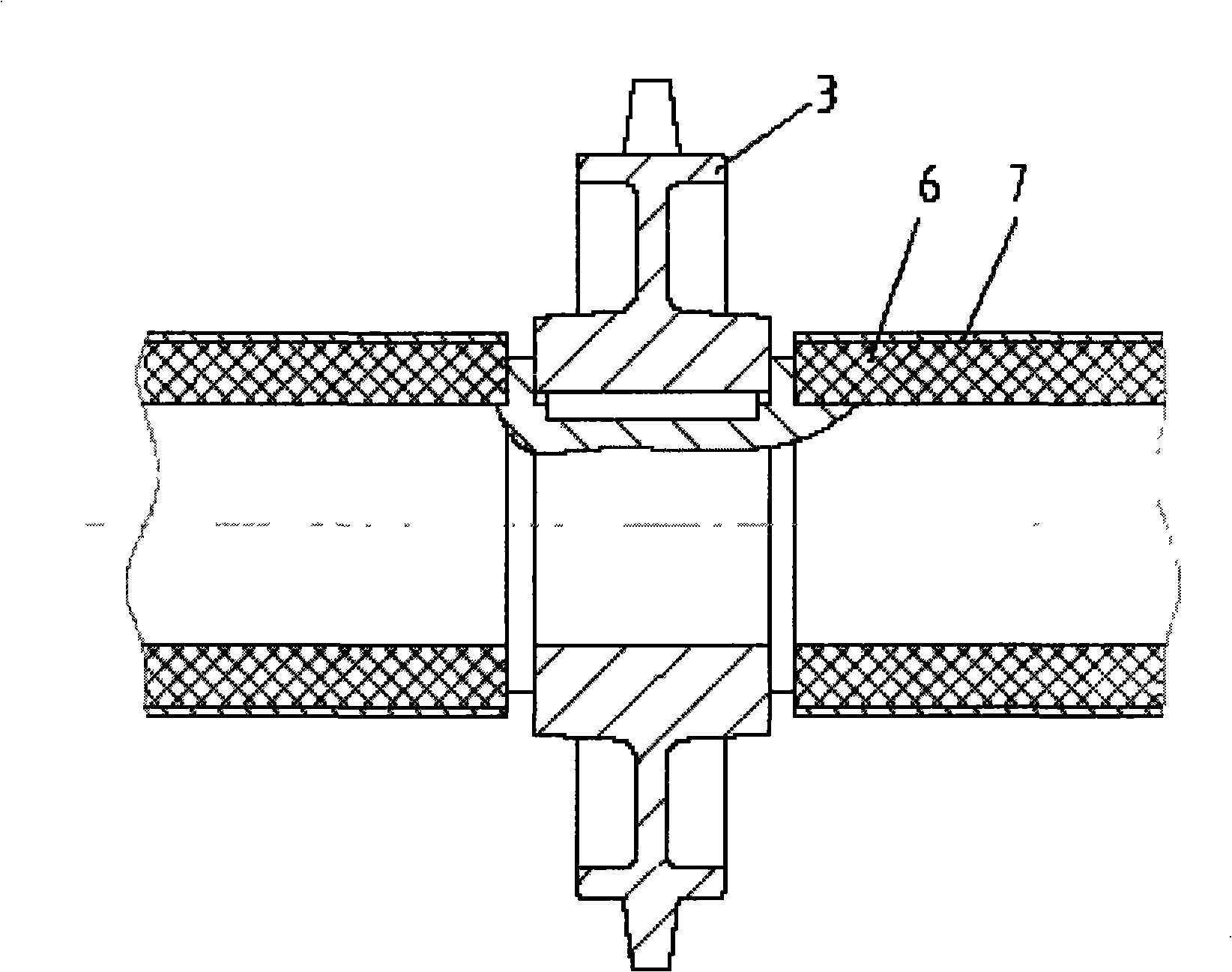
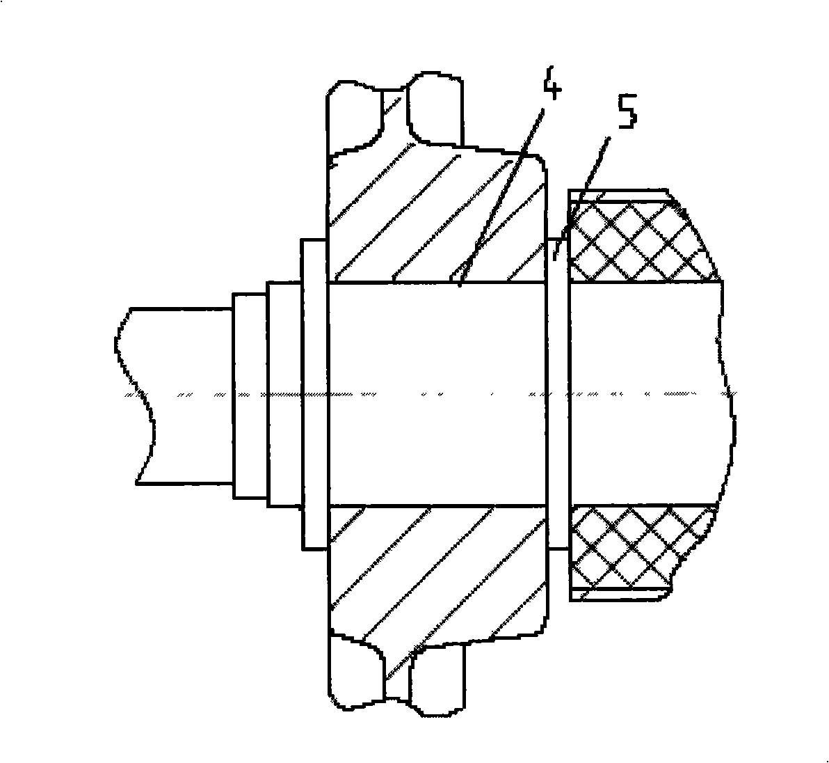
[0022] In the structural diagram of Example 1 shown in Figure 1, 1 is the idler shaft; 2 is the smooth idler, and there are three on each idler, all of which are split, and the smooth idler 2 is empty on the idler shaft 1 forms a clearance fit; 3 is a sprocket, one of which is split, and the sprocket 3 is connected with the idler shaft 1 through a flat key 4, and its axial direction is limited by the shoulder 5 on the idler shaft 1 Move to meet the needs of the grate...

Embodiment 2

[0024] In this embodiment, only the idler roller whose sum of smooth idlers and sprockets is 6 on the idler roller is described.

[0025] In the schematic structural diagram of embodiment 2 shown in Figure 4, 1 is the idler shaft; 2 is the smooth idler, and there are four on each idler, all of which are split, and the smooth idler 2 is installed through the sliding bearing 8 On the idler shaft 1, the sliding bearing 8 is a gray cast iron sliding bearing, and the half-bearing bush of the sliding bearing 8 is inlaid on the smooth supporting roller 2, which can be replaced together with the smooth supporting roller 2; 3 is a sprocket, and there are 2, for Split type, the sprocket 3 is connected with the idler shaft 1 through the flat key 4 and its axial movement is restricted by the shoulder 5 on the idler shaft 1, so as to meet the need for guiding the grate bed; 6 is heat insulation material , the effect is to reduce the heat of the idler shaft 1, and 7 is a heat insulation sle...


PUM


Abstract

A chain grate carrier roller comprises a carrier roller shaft, a smooth riding wheel and a chain wheel. The invention is characterized in that the smooth riding wheel is sheathed on the carrier roller shaft in an idle way. The invention aims at ensuring that the smooth riding wheel can freely rotate relative to the carrier roller shaft, when the chain grate operates, the smooth riding wheel and the chain wheel can rotate at different velocity, so that the pure rolling relationship between the chain wheel and the chains of the chain grate and between the smooth riding wheel and the chains of the chain grate can be guaranteed, the additional resistance caused by relative sliding between the smooth riding wheel and the chains can be avoided, and the abrasion and the drive energy consumption can be reduced.

Description

technical field [0001] The invention relates to a chain grate idler roller, which belongs to a key part of the chain grate. Background technique [0002] The grate machine is a kind of equipment used for material roasting. The supporting roller is used to support the grate bed of the chain grate machine, which is a key part of the chain grate machine. Its basic structure is to fix the sprocket with sprocket teeth and the smooth idler without sprocket teeth on the idler shaft through key connection. The function of the smooth support roller is to support part of the weight of the grate bed; the function of the sprocket is to guide the grate bed through the engagement with the chain on the grate bed, and bear part of the weight of the grate bed at the same time. The main disadvantages of existing grate rollers are that since both the sprocket and the smooth roller are keyed on the same shaft, their rotational speed must be the same, and the grate bed as a whole, in which all ...

Claims


Application Information

Patent Timeline
IPC IPC(8): F27B21/08B65G23/06B65G39/02
Inventor 杨东进姚朝胜魏新民刘建国钱纲黄东生
Owner SHANDONG PROVINCE METALLURGICAL ENG CO LTD
Why Eureka
Try Eureka