A wind turbine yaw control method

A control method and yaw control technology, applied in the control of wind turbines, engine control, engine control parameters, etc., can solve the problems of obvious hysteresis, poor accuracy, etc., to increase power generation, reduce extra load, and improve power capture Effect

Active Publication Date: 2020-02-07
ZHEJIANG UNIV
View PDF3 Cites 0 Cited by
  • Summary
  • Abstract
  • Description
  • Claims
  • Application Information

AI Technical Summary

Problems solved by technology

[0005] Chinese patent application CN102797629A (a kind of control method, controller and control system of wind turbine) and CN103061980A (feedforward control system and control method of wind turbine based on laser wind measuring radar) are all aimed at the measured value of traditional anemometer In order to solve the problem of poor accuracy, a method of using the laser radar anemometer to obtain the wind condition signal and send it to the main control system for the pitch control of the wind turbine is provided. The maximum wind energy capture of the wind turbine is realized through the pitch control, which improves the Phenomenon of poor measurement accuracy
However, frequent manual intervention is required for manual adjustment, and finally adjusted through the wind vane, the hysteresis is obvious

Method used


Image

  • A wind turbine yaw control method
  • A wind turbine yaw control method
  • A wind turbine yaw control method

Examples


Embodiment 1

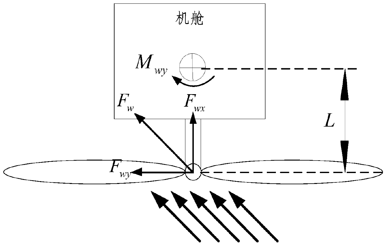
[0058] Such as image 3 As shown, the force of the horizontal axis wind turbine when the wind direction is not aligned with the impeller, then

[0059] f wy =F w sinθ ε =pAcosθ ε sinθ ε

[0060] m wy =F wy ·L

[0061] The torque of the wind direction to the wind rotor can be calculated as

[0062]

[0063] In the formula, θ ε Indicates the angle between the wind direction and the normal direction of the wind rotor, F w Indicates the force of the wind on the impeller, F wx Indicates the component of the wind force on the x-axis, F wy Indicates the component of the wind force on the y-axis, and L indicates the distance between the center of the tower and the impeller in the x-axis direction.

[0064] It can be seen that the torque caused by the wind direction depends on v and θ ε , when the wind speed reaches or exceeds the rated wind speed and the angle between the wind direction and the normal direction of the wind rotor reaches 45°, M wy Reaches the maximum ...

Embodiment 2

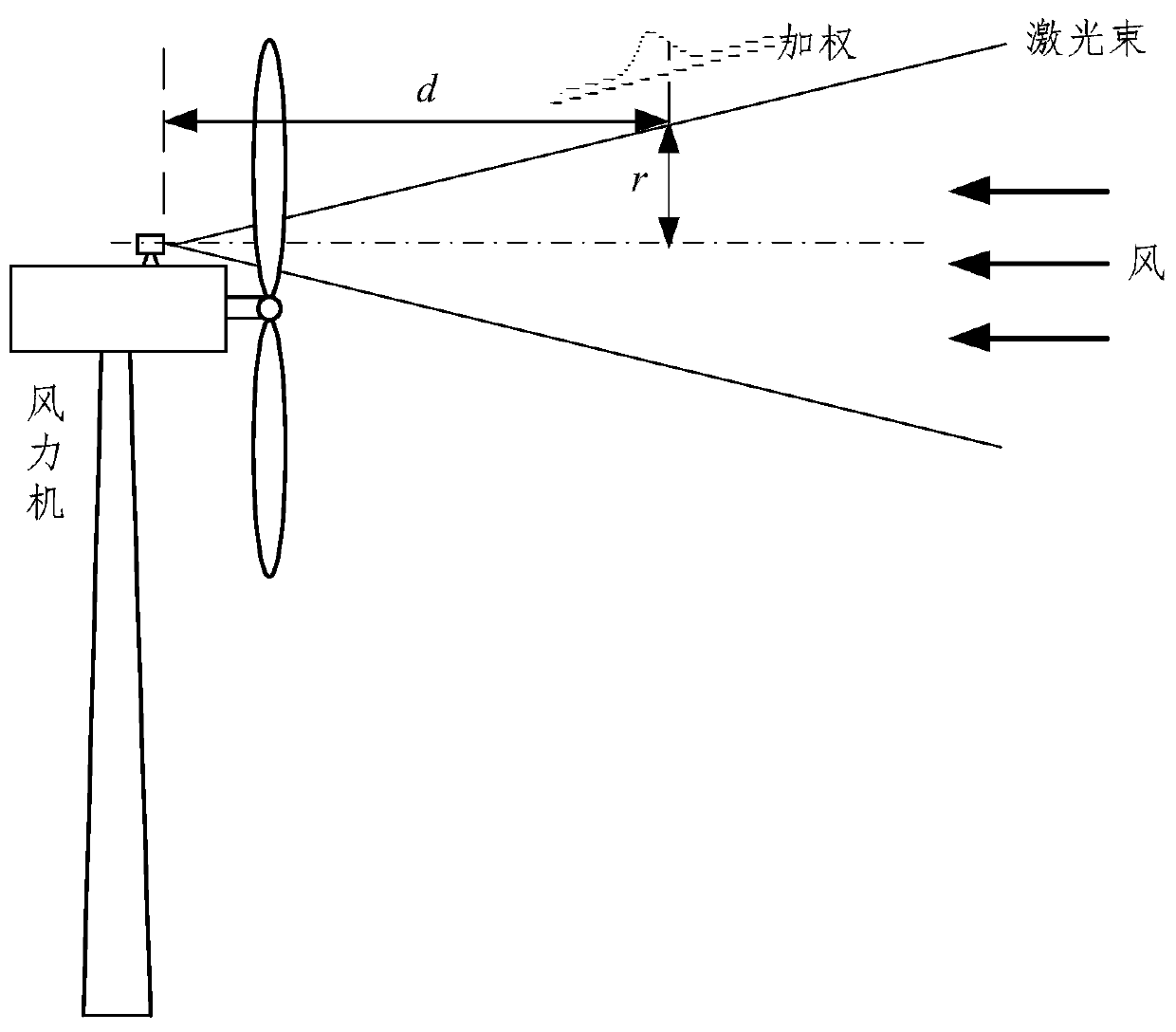
[0071] Such as figure 2 As shown, the scanning method of wind lidar is mostly in the form of conical scanning, d is the measurement distance, and r is the scanning radius. In order to reduce the error in the processing of Doppler frequency shift in single-point measurement, the wind speed results are generally The multiple wind speeds are spatially averaged, and the weight is configured according to the distance of the reflected photon from the focal point, and then the wind speed in the direction of a light is obtained. The distance weighted by the radar measurement is as follows: figure 2 shown in the middle curve.

Embodiment 3

[0073] In step S2 described in Embodiment 1, the specific method for calculating the inversion wind speed and inversion wind direction is:

[0074] First calculate the wind speed and wind direction on the upper beam plane as:

[0075]

[0076] UD=arctan2(v y ,v x )

[0077] In the formula, UWS: upper beam plane wind speed; UD: upper beam plane wind direction.

[0078] in addition,

[0079]

[0080] In the formula, RWS 1 : line-of-sight wind speed measured at line-of-sight 1 on the upper plane; RWS 2 : line-of-sight wind speed measured at line-of-sight 2 on the upper plane; θ t : half of the angle between the left and right beam planes; θ s : half of the angle between the upper and lower beam planes.

[0081] The vertical wind shear is:

[0082]

[0083] The rate of change of vertical wind direction is:

[0084] VD=(UD-DD) / (2X t tanθ s )

[0085] In the formula, DWS: down beam plane wind speed; DD: wind direction; H lidar : Radar installation height; H...


PUM


Abstract

The invention discloses a wind turbine yaw control method. A wind turbine is a horizontal shaft wind driven generator. The wind turbine yaw control method includes the following steps: S1, sight linewind speed and wind direction data at the corresponding position are measured through a laser radar arranged on a cabin or a rotating shaft of the wind turbine; S2, inversion wind speed and wind direction data of the radar are obtained through the sight line wind speed and wind direction data measured by the laser radar; S3, the inversion wind speed and wind direction data are substituted into a wind evolution model, and predicted current wind information of the wind turbine is calculated; and S4, wind turbine yaw control is conducted according to the calculated evolution wind speed and wind direction information and current cabin wind direction deviation information returned by a wind indicator. Wind turbine yaw without speed impact is achieved, and yaw stability is improved; the yaw lifeinterval is optimized, the power capture of the wind turbine is improved, and thus the generating capacity of the wind turbine is increased; and the additional load is lowered, and the service life of a yaw system is prolonged.

Description

technical field [0001] The invention relates to the technical field of wind power, in particular to a wind turbine yaw control method. Background technique [0002] As a new type of energy, wind energy has broad application prospects. However, wind energy has the characteristics of non-stationarity, randomness, and low energy density. These characteristics lead to constant changes in wind speed and direction, so that wind turbines cannot always face the wind, thereby reducing the utilization efficiency of wind energy. The yaw control system is a unique servo system for wind turbines. Its main function is to control the wind wheel to track the changing wind direction and improve power capture. [0003] The traditional yaw control system detects the wind direction and wind speed through the wind speed and direction sensor, and sends the detected wind direction and wind speed data to the controller for processing. The controller sends commands to perform corresponding yaw oper...

Claims


Application Information

Patent Timeline
Patent Type & Authority Patents(China)
IPC IPC(8): F03D7/04
CPCF03D7/0204F03D7/044F03D7/045F05B2270/32F05B2270/321F05B2270/8042Y02E10/72
Inventor 陈文婷张迪刘航林勇刚李伟刘宏伟
Owner ZHEJIANG UNIV
Why Eureka
Try Eureka