Charge Air Cooler

Inactive Publication Date: 2008-07-03
SCANIA CV AB
View PDF12 Cites 9 Cited by
  • Summary
  • Abstract
  • Description
  • Claims
  • Application Information

AI Technical Summary

Benefits of technology

[0004]The object of the present invention is to provide a charge air cooler so constructed as to make it possible to control the flow of compressed air through the cha

Problems solved by technology

When the temperature of the surrounding air is very low, there is also risk that water in liquid form may freeze to become ice inside the ch

Method used


Image

  • Charge Air Cooler
  • Charge Air Cooler
  • Charge Air Cooler

Examples


Example

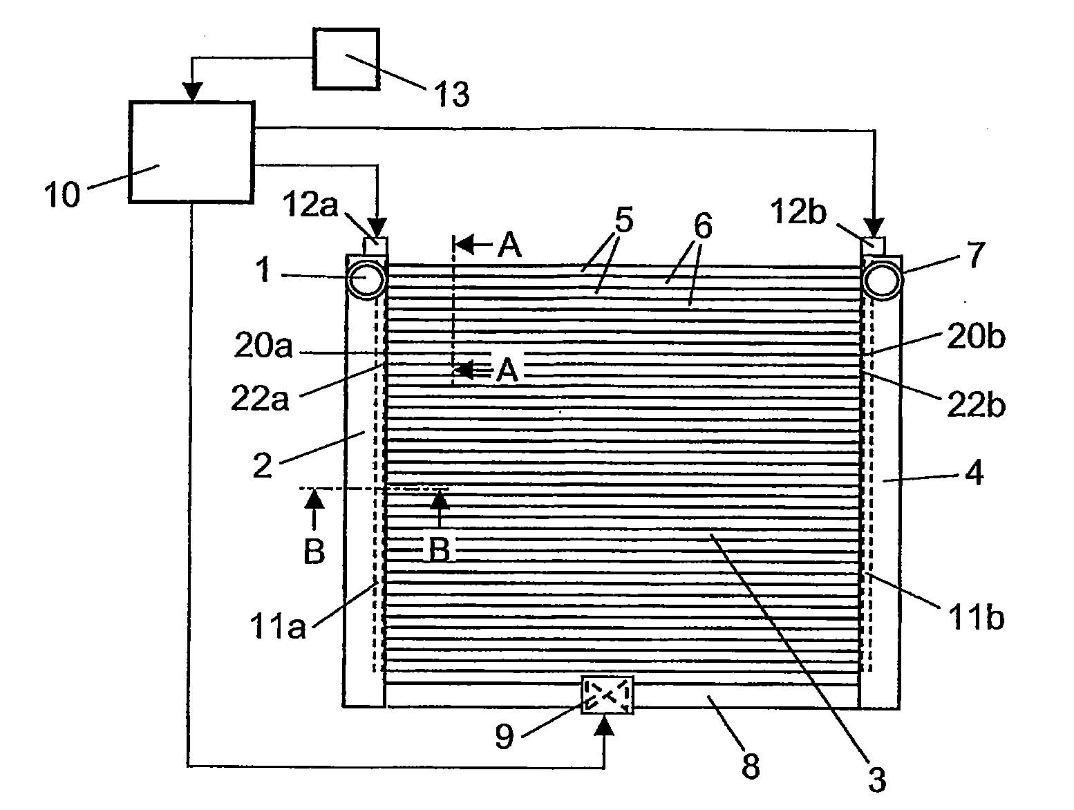
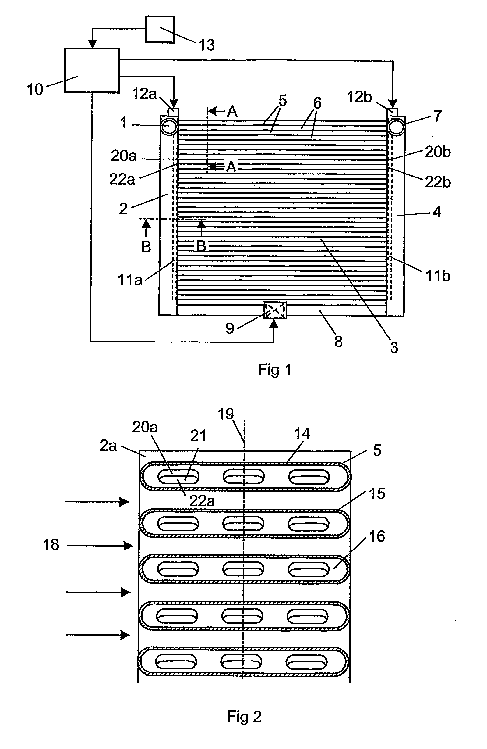
[0016]FIG. 1 depicts a charge air cooler which may for example be fitted at a front portion of a vehicle which is powered by a supercharged combustion engine. A supercharged combustion engine needs a supply of compressed air. The function of the charge air cooler is to cool the compressed air before it is led to the combustion engine. The charge air cooler comprises an inlet 1 to a first tank 2 which receives warm compressed air from a compressor. The charge air cooler comprises a cooler package 3 which extends between the first tank 2 and a second tank 4 for receiving cooled compressed air. The cooler package 3 comprises a plurality of tubular elements 5 which extend in a substantially rectilinear manner in a common plane between the first tank 2 and the second tank 4.

[0017]The tubular elements are arranged parallel at a substantially uniform distance from one another so that there are regular gaps 6 between adjacent tubular elements 5. Surrounding air can therefore flow through th...


PUM


Abstract

A charge air cooler comprising at least one tubular element with an internal flow duct for leading compressed air between an inlet aperture and an outlet aperture. A medium at a lower temperature than the compressed air is caused to flow in contact with an outside surface of the tubular element cooling the compressed air in the tubular element when the air is led through the flow duct. A movable control element is arranged close to the inlet aperture or the outlet aperture of the flow duct. A control for the control element provides a variable flow of compressed air through the flow duct as the movable control element is placed in various positions.

Description

BACKGROUND TO THE INVENTION, AND STATE OF THE ART[0001]The present invention relates to a charge air cooler according to the preamble of claim 1.[0002]The amount of air which can be supplied to a supercharged combustion engine of a vehicle depends on the pressure of the air but also on the temperature of the air. Supplying the largest possible amount of air to a supercharged combustion engine entails cooling compressed air in a charge air cooler before it is led to the combustion engine. The charge air cooler is usually situated in front of the conventional radiator of a vehicle. A charge air cooler usually comprises two tanks and a plurality of tubular elements arranged in parallel which connect the tanks to one another. The parallel tubular elements are arranged at a distance from one another so that surrounding cold air can flow between the tubular elements and cool the compressed air in the tubular elements. Depending on the efficiency of the charge air cooler, the compressed ai...

Claims


Application Information

Patent Timeline
IPC IPC(8): F02B29/04
CPCF02B29/0418F02B29/0456F02B29/0475Y02T10/146F28D1/05366F28F27/02F28F2250/06F02B29/0493Y02T10/12
Inventor HAGBERG, MAGNUSPETTERSSON, HENRIK
Owner SCANIA CV AB
Why Eureka
Try Eureka