Liquid crystal display device

a technology of liquid crystal display and illumination device, which is applied in the direction of lighting device details, lighting and heating apparatus, instruments, etc., can solve the problems of backlight becoming heavy, and achieve the effect of reducing the thickness of the illumination device, simplifying the structure, and uniform brightness of the illumination devi

Active Publication Date: 2008-08-07
PANASONIC LIQUID CRYSTAL DISPLAY CO LTD +1
View PDF7 Cites 24 Cited by
  • Summary
  • Abstract
  • Description
  • Claims
  • Application Information

AI Technical Summary

Benefits of technology

[0013]The present invention provides an illumination device having a simplified structure which can simply form a shape of a reflector and, at the same time, can acquire both the uniformity of brightness of the illumination device and the reduction of thickness of the illumination device.
[0014]To be more specific, according to the present invention, a back lid of a lower frame which houses a backlight device therein can be eliminated and hence, a weight of the backlight can be largely reduced. Particularly, the lower frame is often made of a metal and hence, the elimination of the back lid brings about a large weight reduction effect. Further, the elimination of the back lid also brings about the reduction of a part cost and an assembly cost.
[0015]Further, according to the present invention, even when an edge-light-type backlight is used, light from a light source can be directed toward a liquid crystal panel without using a so-called light guide plate thus realizing the reduction of weight and the reduction of cost of the backlight.

Problems solved by technology

However, due to the adhesion of an extra material to the reflection sheet, there arises a drawback that the backlight becomes heavy.

Method used


Image

  • Liquid crystal display device
  • Liquid crystal display device
  • Liquid crystal display device

Examples


embodiment 1

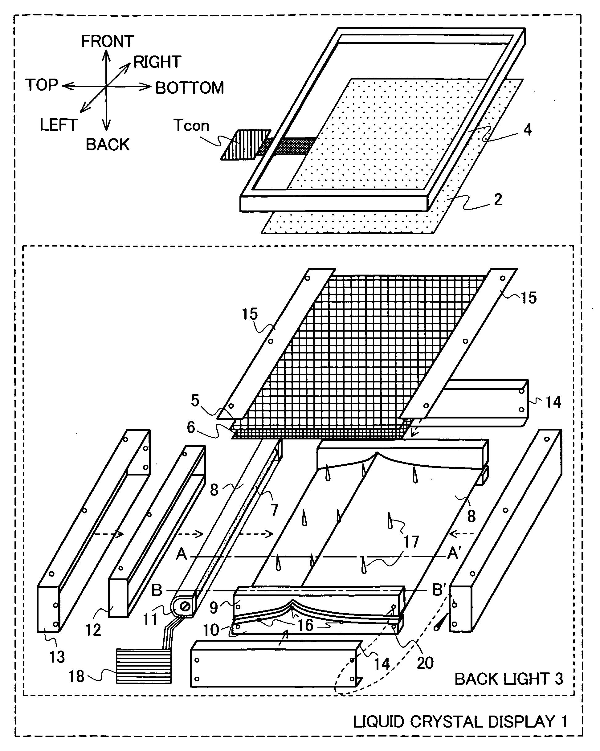
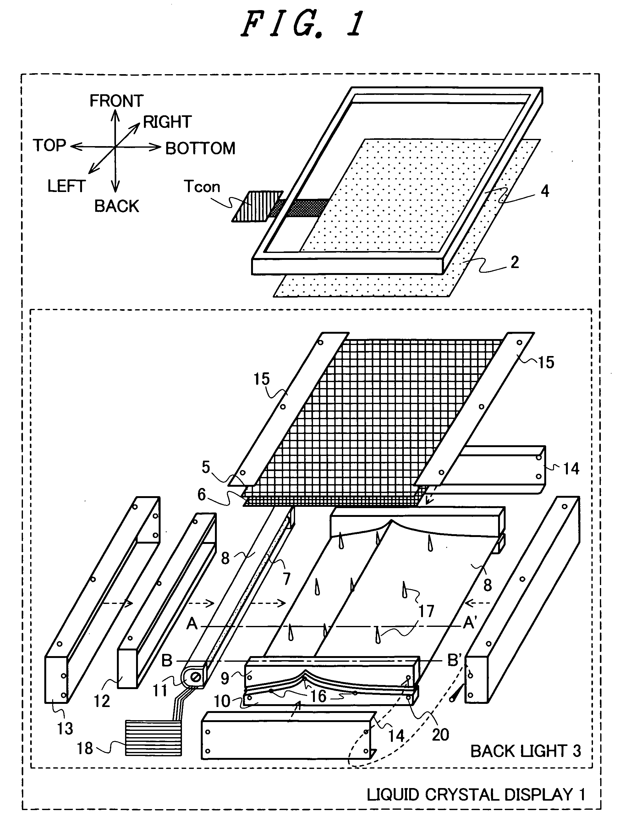
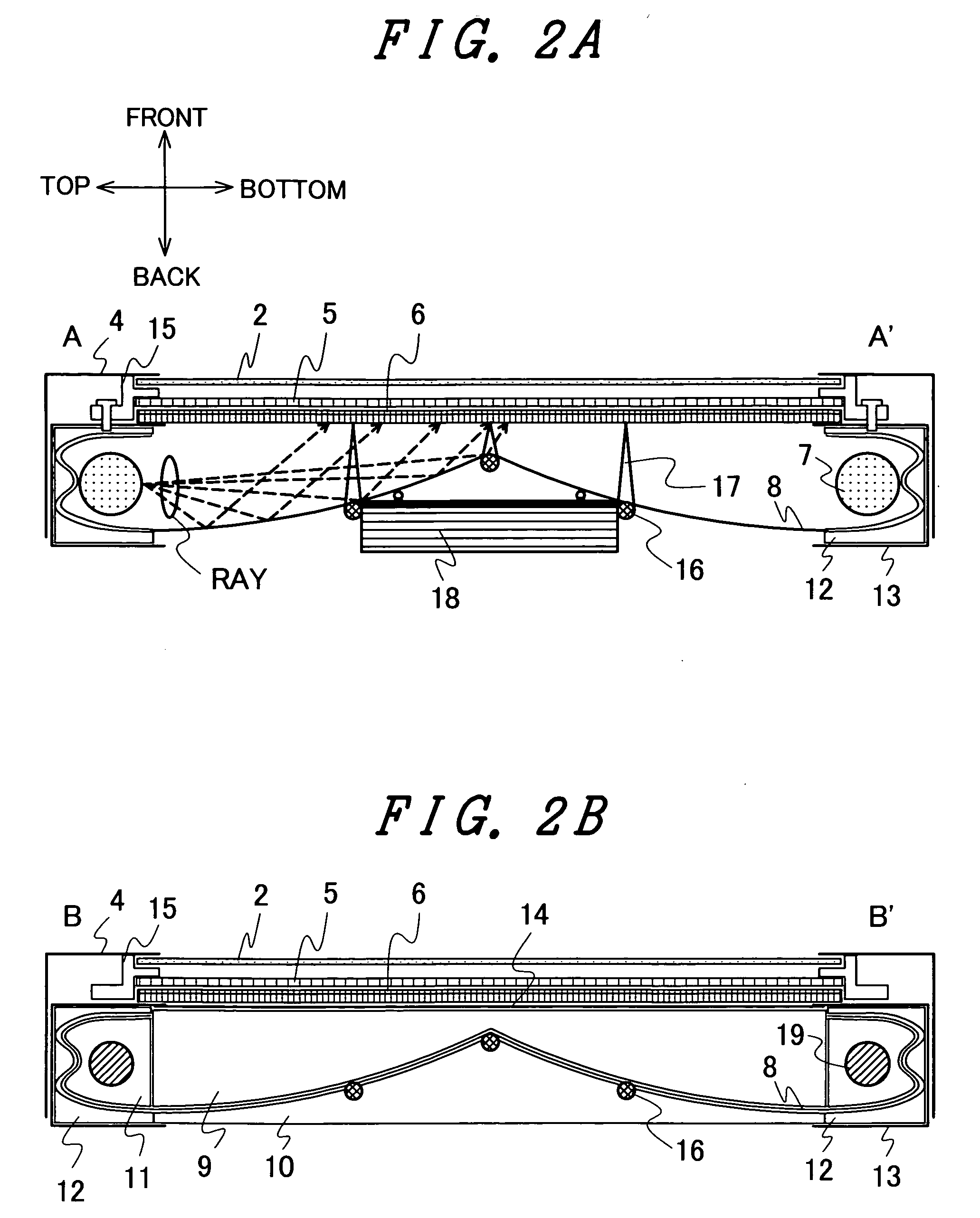
[0029]FIG. 1 is a perspective view showing the essential constitution of a liquid crystal display device 1 (device constituted of members surrounded by an outside frame) according to an embodiment 1 of the present invention. FIG. 2A and FIG. 2B are cross-sectional views taken along a line A-A′ and a line B-B′ in FIG. 1 respectively. Arrows described on a left upper side in FIG. 1 indicate an azimuth of image data to be displayed and an azimuth arranged parallel to a normal direction of a plane of a liquid crystal panel 2 and defining a front surface and a back surface of the liquid crystal display device 1. Azimuths depicted by “up”, “down”, “left” and “right” indicate azimuths within the same plane as a display screen of the liquid crystal panel 2 and indicate azimuths of image data. (Image data corresponding to the upper side is displayed in the direction indicated by “up”. In displaying scenery consisting of the sky and sea, for example, the sky is displayed on the upper side in ...

embodiment 2

[0051]In the embodiment 1, the explanation has been made with respect to the example in which the present invention is applied to the edge-light-type backlight. In the embodiment 2, the explanation is made with respect to a case in which the present invention is applied to the direct-type backlight. FIG. 7 is a perspective view showing the main constitution of a liquid crystal display device 1 according to this embodiment (device constituted of members surrounded by an outer frame). FIG. 8A and FIG. 8B are cross-sectional views taken along a line D-D′ in FIG. 7 and a line E-E′ in FIG. 7. In this embodiment, a light source is formed of an HCFL. It is needless to say that the light source is not limited to the HCFL.

[0052]In a direct-type backlight, when a thickness of the backlight is small (when a distance between the light source and the diffusion plate is small) or when the number of light sources is small, there arises brightness irregularities that a space right above the light s...

embodiment 3

[0057]This embodiment shows a case in which the present invention is applied to an edge-light-type backlight and mainly focuses on the back surface structure.

[0058]FIG. 9A to FIG. 9C are views showing the structure of a backlight as viewed from a back surface of the backlight. FIG. 9A shows the structure of the backlight shown in FIG. 1 as viewed from a back surface of the backlight, wherein the detail of lines extending toward lamps from a Tcon and a light source drive circuit 18 is added. The Tcon is fixed to a metal cover 13 and amounting bar 16. Out of lines extending toward the light source 7 from the light source drive circuit 18, for setting a high-voltage-side line 22 shorter than a low-voltage-side line 23, the light source drive circuit 18 is arranged on an end portion (left end in the drawing) of the backlight.

[0059]FIG. 9B shows an example which increases the structural strength by inserting a beam 24 between the mounting bar 16 and the reflector-shape forming member 9 o...


PUM

PropertyMeasurementUnit
thicknessaaaaaaaaaa
sizeaaaaaaaaaa
diameteraaaaaaaaaa

Abstract

The present invention provides a light-weighted backlight capable of ensuring a sufficient light quantity at a low cost. A backlight is arranged below a liquid crystal panel. A light source is arranged in the vertical direction with respect to a screen of the liquid crystal panel so that light from the light source is directed toward the liquid crystal panel by a reflector. Due to such a constitution, the reflector can also function as a back lid of the backlight. Further, the reflector plays a role of directing the light from the light source toward the liquid crystal panel and hence, a light guide plate can be omitted. Due to such a constitution, the present invention can realize the reduction of weight and cost of the backlight or the liquid crystal display panel.

Description

[0001]The present application claims priority from Japanese application JP2007-023066 filed on Feb. 1, 2007, the content of which is hereby incorporated by reference into this application.BACKGROUND OF THE INVENTION[0002]The present invention relates to an illumination device, and more particularly to a backlight used in a liquid crystal display device.[0003]A TFT (Thin Film Transistor) type liquid crystal display device has been popularly used as a display device of a liquid crystal television receiver set, a personal computer or the like. The liquid crystal display device is constituted of a liquid crystal panel having a drain driver and a gate driver arranged on a periphery thereof and a back light radiating light to the liquid crystal panel.[0004]The backlight is classified into an edge-light-type backlight and a direct-type backlight. One of crucial tasks that both backlights possess is the acquisition of a uniform backlight by suppressing brightness irregularities.[0005]As one...

Claims


Application Information

Patent Timeline
Patent Type & Authority Applications(United States)
IPC IPC(8): G02F1/1335
CPCG02F1/133605G02F1/133615G02F1/133608
Inventor IMOJO, YOSHIHIROSEKIGUCHI, YOSHIFUMI
Owner PANASONIC LIQUID CRYSTAL DISPLAY CO LTD
Why Eureka
Try Eureka