Fire Suppression System and Emergency Annunciation System

Active Publication Date: 2008-09-04
TYCO FIRE PRODS LP
View PDF47 Cites 8 Cited by
  • Summary
  • Abstract
  • Description
  • Claims
  • Application Information

AI Technical Summary

Benefits of technology

[0015]The faceplate may contain one or more mounting screw bosses, each with integral containment boundary diaphragms to prevent grease, dirt or grime from entering behind the pull station. These screw bosses may be located to correspond with the associated screw bosses found on electrical junction boxes (such as shallow or deep electrical junction boxes). The containment boundary diaphragm holes aligned with the electrical junction box mounting screw bosses may be punched out to enable the faceplate to be screw mounted to the electrical junction box. Removal of the containment boundary diaphragms thus may enable an assembly screw to be inserted through the hole and momentarily captured in that hole to enable positioning of the faceplate over the electrical junction box without the screws falling from the holes. The faceplate may further include one or more indicia that is a color or texture that is different from another portion of the faceplate (such as a contrasting color indicia). For example, one or more of the words that are on the faceplate may be red, fluorescent, or glow in the dark in order to differentiate the words (and the faceplate) from the surroundings (such as an aluminum background).
[0016]The pull station faceplate may also include functional standing protective barriers that may protect the pull knob and pull handle from side impact and may provide a protective and functional means to capture the ends of the break rod when the pull knob is installed and ready to be activated. Further, the faceplate may include storage for maintenance components. The maintenance components may include maintenance parts such as spare break rods or copper compression fittings.
[0017]The faceplate of the pull station may be integrated with a pulley block system. The pulley block system may securely engage into and with corresponding features of the faceplate. For example, the pulley block system may be press fitted into the faceplate of the pull station. The combination may create an assembly that routes the wire rope in the direction of and on centerline to the flexible conduit or to rigid conduit as it enters the electrical junction box. The faceplate and pulley block each may contain multiple and corresponding inter-engaging features to enable numerous wire rope direction routing capabilities. Specifically, the pulley block and pulley may be configured in various ways to enable

Problems solved by technology

However, using rigid EMT tubing 130 and 90 degree elbows 150 is very labor intensive, expensive and not preferable to some building wall geometries and accesses.
Because the pre-shaped rigid conduit tubing does not include pulley elbows 150, the wire rope 140 encounters high friction, making pulling of the pull handle difficult.
Disadvantages to this method include the excess cost associated with the pulley system along with the lack of controlled routing.
A simple loss of wire rope tension might result in the wire rope “

Method used


Image

  • Fire Suppression System and Emergency Annunciation System
  • Fire Suppression System and Emergency Annunciation System
  • Fire Suppression System and Emergency Annunciation System

Examples


Example

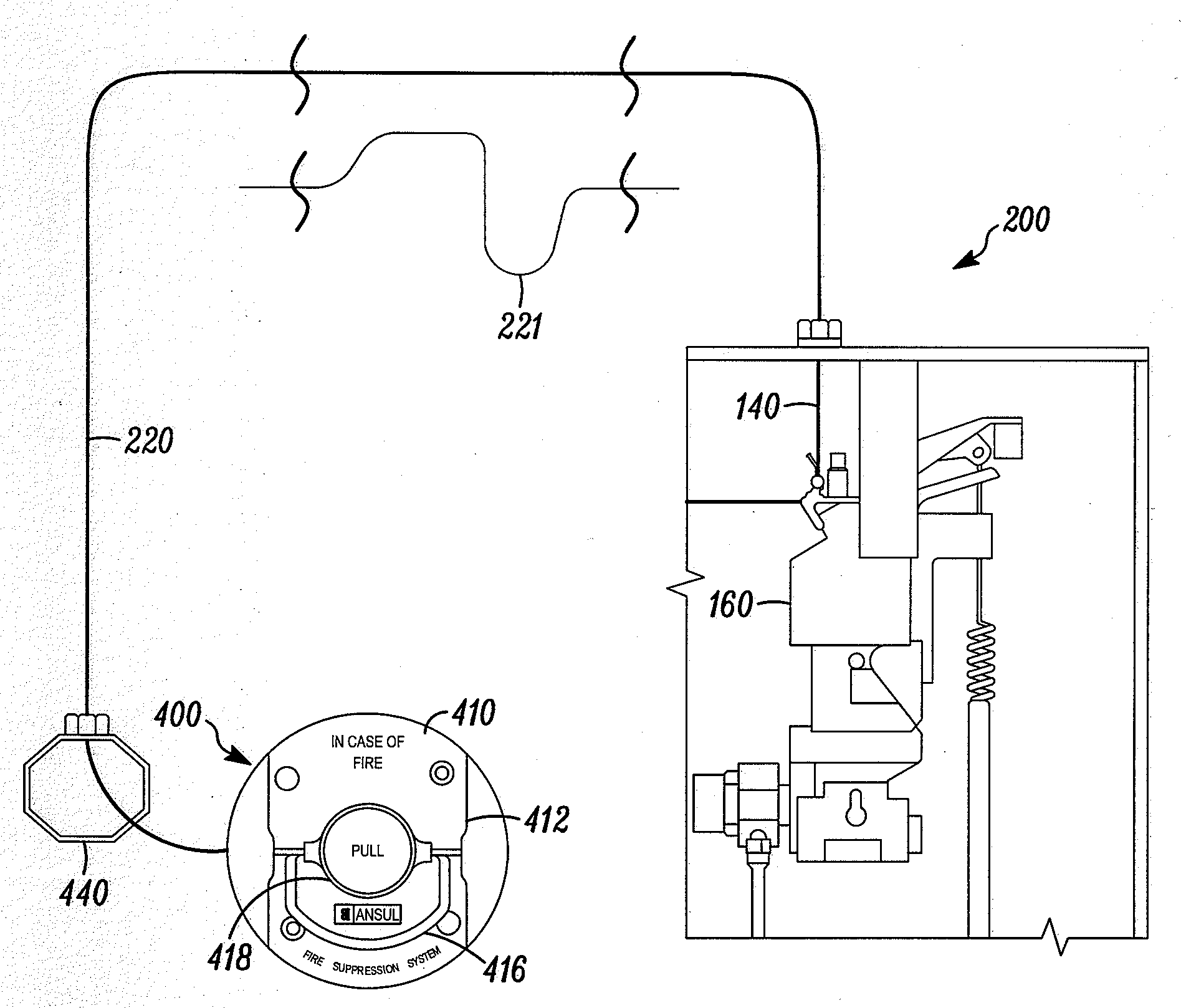
[0084]FIG. 6 is a block diagram illustrating a mechanical system for connecting the pull handle 416 of pull station 400 to the release mechanism 160 of the fire suppression system using a wire rope 140 contained within a flexible conduit 220. An example of the release mechanism 160 is a panel, such as the Ansul AUTOMAN® panel. Another example of the release mechanism 160 is a valve. Alternatively, flexible conduit 220 may be used to connect pull station 110 (shown in FIG. 1) with the release mechanism 160.

[0085]The flexible conduit 220 may be composed of a variety of types of conduits, such as a Bowden conduit and a braided conduit, as shown in more detail in FIGS. 5A-C. However, the flexible conduit is not limited to these types of conduits. The flexible conduit 220 may include a liner, a liner wrap, and an outer jacket. Though, the flexible conduit 220 does not need to include each of the liner, the liner wrap and the outer jacket. For example, the outer jacket need not be include...


PUM


Abstract

A fire suppression and annunciation system using a flexible conduit and a wire rope is provided. The wire rope may be connected to a knob assembly at a universal pull station and to a release mechanism of the fire suppression system. An operator may pull a handle of the knob assembly at the universal pull station, thereby activating the release mechanism to release fire suppression agent. A flexible conduit may house the wire rope along at least a part of the connection from the universal pull station to the release mechanism. A material on the liner of the flexible conduit and/or on the wire rope may be used to reduce the coefficient of friction of wire rope in the flexible conduit. The fire suppression system may further include a pulley block system connected to the universal pull station. The pulley block system may comprise bearings, and may lower the force necessary to activate the release mechanism.

Description

REFERENCE TO RELATED APPLICATION[0001]This application claims the benefit of U.S. Provisional Application No. 60 / 904,551, filed Mar. 2, 2007, the entirety of which is hereby incorporated by reference.BACKGROUND OF THE INVENTION[0002]1. Technical Field[0003]The present invention relates to a fire suppression system activated manually (such as by a pull knob or electronically) or activated automatically (such as by the detection links in the detection line).[0004]2. Related Art[0005]Fire suppression systems may be activated using a pull knob. The pull knob may be located in the path of egress or near an operator of a machine, such as an oven, popcorn machine, etc., and may be used to activate the fire suppression system. In the event of a fire, the operator may pull the pull knob, thereby activating a release mechanism of the fire suppression system.[0006]The release mechanism may indirectly or directly cause the fire suppression agent to be dispensed, thereby reducing or eliminate th...

Claims


Application Information

Patent Timeline
IPC IPC(8): A62C3/00G08B5/36
CPCG08B25/12A62C37/00A62C3/006A62C35/023G08B17/00
Inventor ERVA, MICHAEL WALTERHALT, THOMAS MICHAELBJORKMAN, DONALD MARVINCHERNETSKI, BRIAN FLOYDRUOHONEN, DOROTHYBENDA, STEVEN JOHNNEUMANN, MARK
Owner TYCO FIRE PRODS LP
Why Eureka
Try Eureka