Remote diagnostic system for robots

a robot and diagnostic system technology, applied in the direction of electric programme control, program control, instruments, etc., can solve the problems of high communication cost, and achieve the effects of low communication cost, high communication security, and cost-effectiveness

Active Publication Date: 2008-10-09
ABB (SCHWEIZ) AG
View PDF18 Cites 25 Cited by
  • Summary
  • Abstract
  • Description
  • Claims
  • Application Information

AI Technical Summary

Benefits of technology

[0005]If, in a robot monitoring system, a remote service center is established to perform the monitoring of a high number of robots spread at a plurality of plants at different geographic locations, an optimization of communication traffic between each individual robot of the system and the remote service center plays a major role to enable delivery of cost effective services (diagnostics) to a customer. One

Problems solved by technology

Said service unit is in turn connected to a remote connector server at a remote servic

Method used


Image

  • Remote diagnostic system for robots
  • Remote diagnostic system for robots
  • Remote diagnostic system for robots

Examples


Embodiment Construction

[0025]Below the invention will be explained in greater detail by description of embodiments with reference to the accompanying drawings.

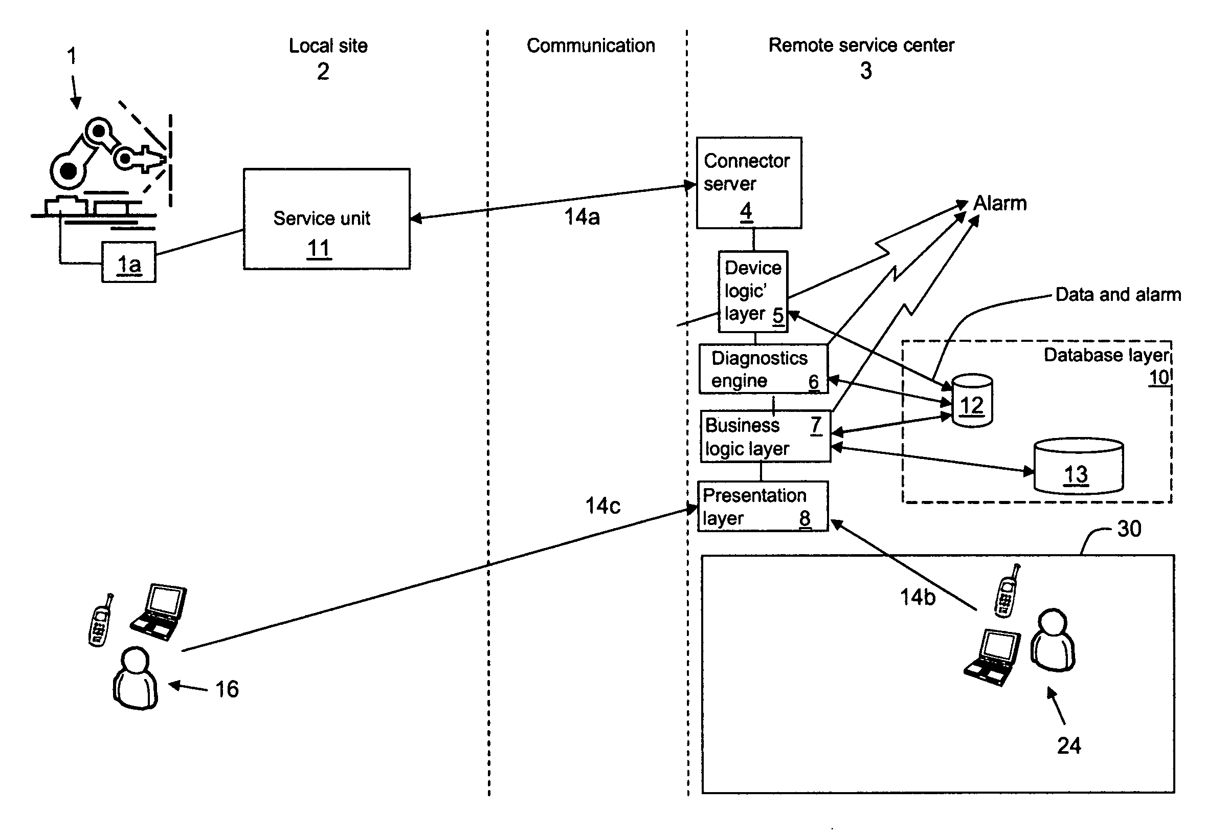
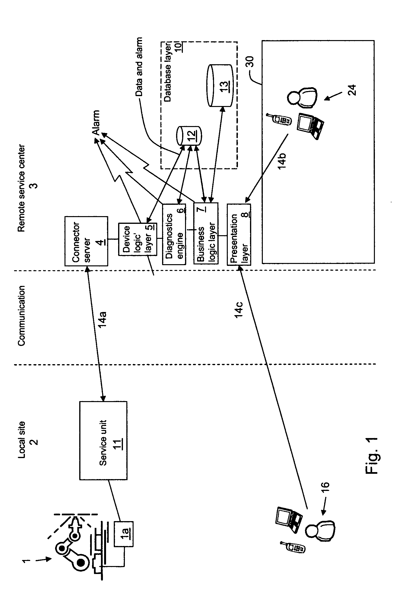
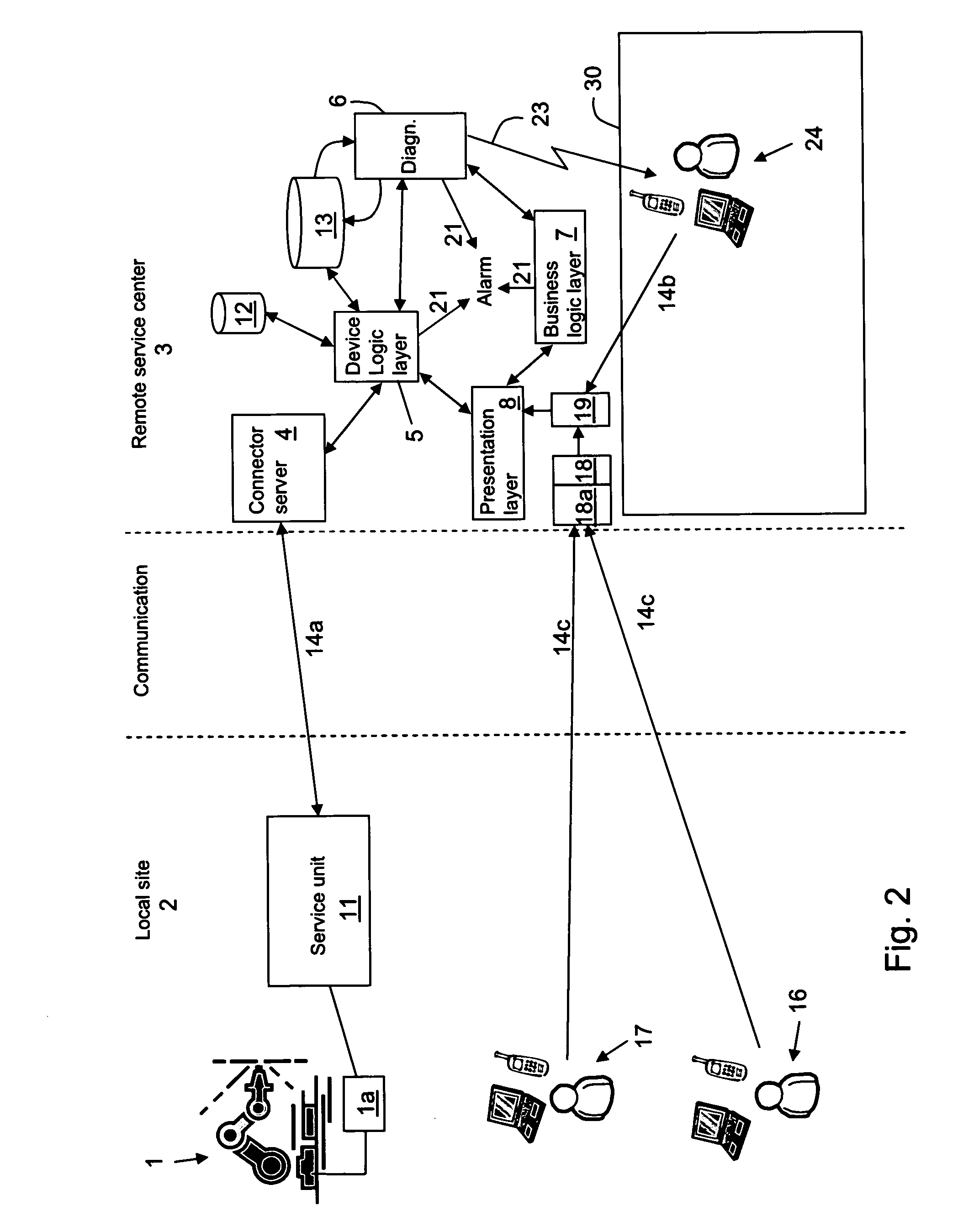
[0026]The general architecture of the remote service center is structured to function as, among others, a central data storage with a web interface. A device logic layer will make the interface with customer equipment and will handle the communication between the servers and databases at the remote service center and the local site at the customer.

[0027]FIG. 1 shows a brief overview of the remote diagnostic system for robots according to one aspect of the invention and is explained more in detail in the following. A robot 1 at a customer site, herein called a local site 2, depicted in the system represents only one of the plurality of robots that can be included at the local site in the system. The local site 2 further represents a plurality of local sites (at least two), which can be included in the remote diagnostic system.

[0028]In the system ther...


PUM


Abstract

A remote diagnostic system for robots including a number of at least two robots, wherein a controller of each robot of the system is locally connected to a service unit provided with local processing power, a remote service center provided with a connector server is arranged, and a communications infrastructure for transferring packets of information between a controller of a robot of the system and connector server via the service unit is arranged for performing remote monitoring and diagnostics at the remote service center, wherein the communications infrastructure uses internet and/or GPRS communication lines.

Description

CROSS-REFERENCE TO RELATED APPLICATIONS[0001]This application claims priority to European patent application 07102279.2 filed 13 Feb. 2007.TECHNICAL FIELD[0002]The present invention relates to a system of monitoring a plurality of robots spread at different locations at a remote service center by means of information exchange between individual robots and the remote service center.BACKGROUND OF THE INVENTION[0003]Common diagnostic systems for robot controllers consist of either a computational unit in the robot controller or diagnostics computations performed in a PC connected to the robot controller. Common to these existing solutions is the use of a high bandwidth of data signals that flow from the controller at the diagnostics computations. Diagnostics has conventionally been performed locally at the controller or at a device which has a high bandwidth connection to the controller.[0004]US published application 2006 / 0206289 discloses a system of monitoring a plurality of robots f...

Claims


Application Information

Patent Timeline
IPC IPC(8): G06F19/00H04L9/00
CPCB25J9/1674G05B2219/33284G05B2219/39412
Inventor BLANC, DOMINIQUEALT, JEAN-CHRISTOPHEEKELUND, ANDERSNYMARK, JESSICAMURPHY, STEVE
Owner ABB (SCHWEIZ) AG
Why Eureka
Try Eureka