In-home receiving terminal system

a terminal system and terminal technology, applied in the field of in-home receiving terminal system, can solve the problems of unfavorable cable television broadcasting, low cost, and high fee, and achieve the effect of restricting the viewing of cable television broadcasting

Inactive Publication Date: 2008-10-30
PANASONIC CORP
View PDF4 Cites 9 Cited by
  • Summary
  • Abstract
  • Description
  • Claims
  • Application Information

AI Technical Summary

Benefits of technology

[0010]Therefore, an object of the present invention is to provide an in-home receiving terminal system capable of restricting viewing of cable television broadcasting by any receiving terminal device outside the subscriber's house.

Problems solved by technology

However, under such a subscriber contract with a plurality of receiving terminal devices, subscribers are charged by the number of receiving terminal devices, and therefore they have to pay a high fee which seems to be relatively expensive.
In this case, the subscriber or the non-subscriber unfairly views cable television broadcasting without paying the fee for one receiving terminal device that should normally be paid to the cable television broadcaster.
That is, the receiving terminal device under contract is unfairly used, so that the cable television broadcaster is not able to receive a legitimate fee.
However, such viewing restrictions based on the viewing key are not effective if any sub-terminal device unfairly lent to the non-subscriber is on the cable television circuit.

Method used


Image

  • In-home receiving terminal system
  • In-home receiving terminal system
  • In-home receiving terminal system

Examples


Embodiment Construction

[0023]Hereinafter, an in-home receiving terminal system according to an embodiment of the present invention will be described with reference to FIGS. 1, 2, and 3.

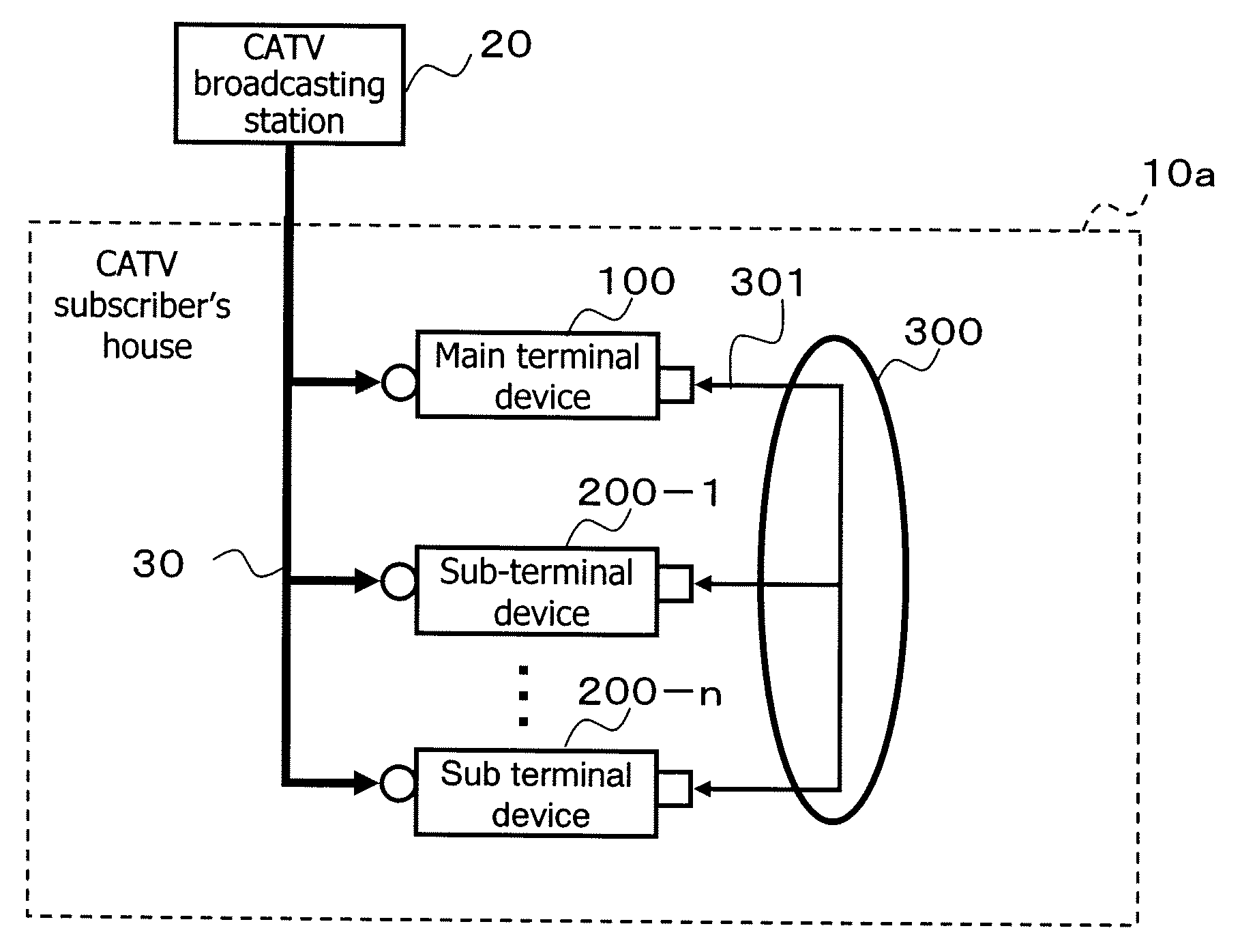
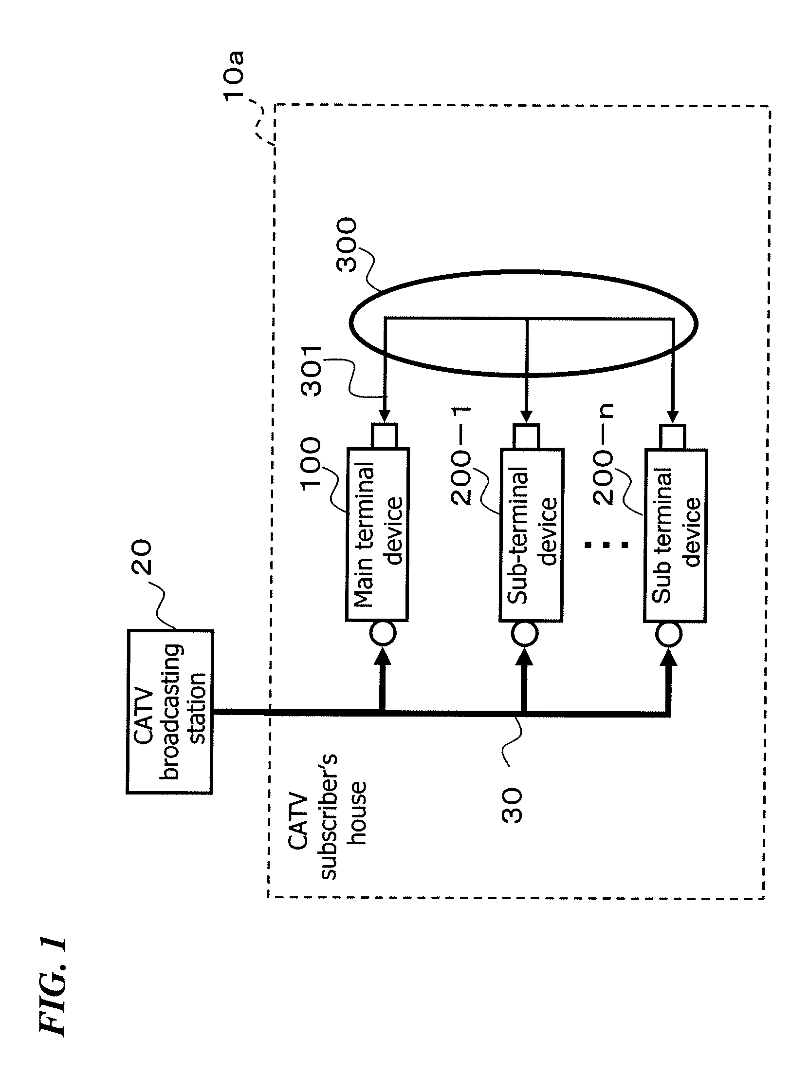
[0024]FIG. 1 illustrates the basic configuration of the in-home receiving terminal system according to the present embodiment. The in-home receiving terminal system 10a consists of one main terminal device 100 and n sub-terminal devices 200-1 to 200-n (where n is an integer of 2 or higher).

[0025]The in-home receiving terminal system 10a is installed in the house of a subscriber (a CATV subscriber's house), and connected to a cable television broadcasting station 20 by a cable television circuit 30. That is, the main terminal device 100 and the sub-terminal devices 200-1 to 200-n are connected to the cable television circuit 30. Note that television programs are distributed via the cable television circuit 30.

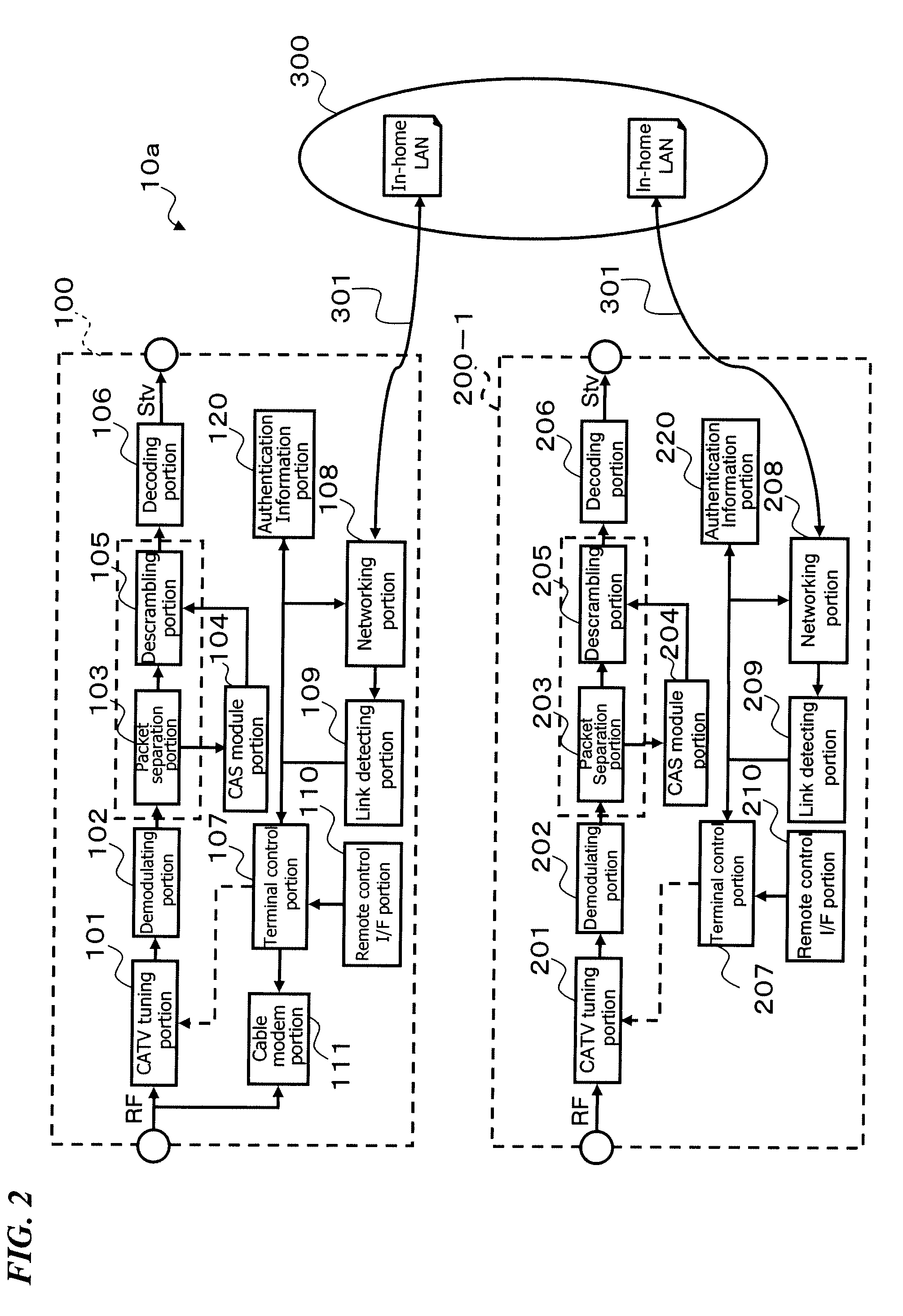
[0026]In addition, the main terminal device 100 and the sub-terminal devices 200-1 to 200-n are connected to an in-ho...


PUM


Abstract

Provided is an in-home receiving terminal system capable of detecting that a receiving terminal device is outside a subscriber's house, and restricting viewing of cable television broadcasting by the receiving terminal device outside the subscriber's house. In the in-home receiving terminal system comprising a main terminal device and a sub-terminal device for receiving digital cable television broadcasting, the main terminal device and the sub-terminal device being connected to an in-home network, a link detecting portion of the sub-terminal device detects the status of a link connection with the in-home network, and a terminal control portion of the sub-terminal device controls activation/deactivation of a television reception tuner based on the detected status of the link connection.

Description

FIELD OF THE INVENTION[0001]The present invention relates to an in-home receiving terminal system consisting of a plurality of receiving terminal devices under the cable television subscriber contract.BACKGROUND OF THE INVENTION[0002]As for cable television broadcasting, it is often the case that one receiving terminal device is used per subscriber contract. In recent years, however, an increasing number of subscribers are using a plurality of receiving terminal devices per contract for the purpose of viewing programs in different rooms or multichannel viewing. For such subscribers, cable television broadcasters rent a plurality of receiving terminal devices.[0003]However, under such a subscriber contract with a plurality of receiving terminal devices, subscribers are charged by the number of receiving terminal devices, and therefore they have to pay a high fee which seems to be relatively expensive. Accordingly, cable television broadcasters set contract systems in which rental fee...

Claims


Application Information

Patent Timeline
Patent Type & Authority Applications(United States)
IPC IPC(8): H04N7/173H04N21/4363
CPCH04H60/15H04H60/95H04N7/1675H04N21/43615H04N21/4524H04N21/4542H04N21/4623
Inventor SHIOYAMA, KENJIARASHIN, NOBUHIKO
Owner PANASONIC CORP
Why Eureka
Try Eureka