

Playback apparatus
- Summary
- Abstract
- Description
- Claims
- Application Information
AI Technical Summary
Benefits of technology
Problems solved by technology
Method used
Image

Examples
first embodiment
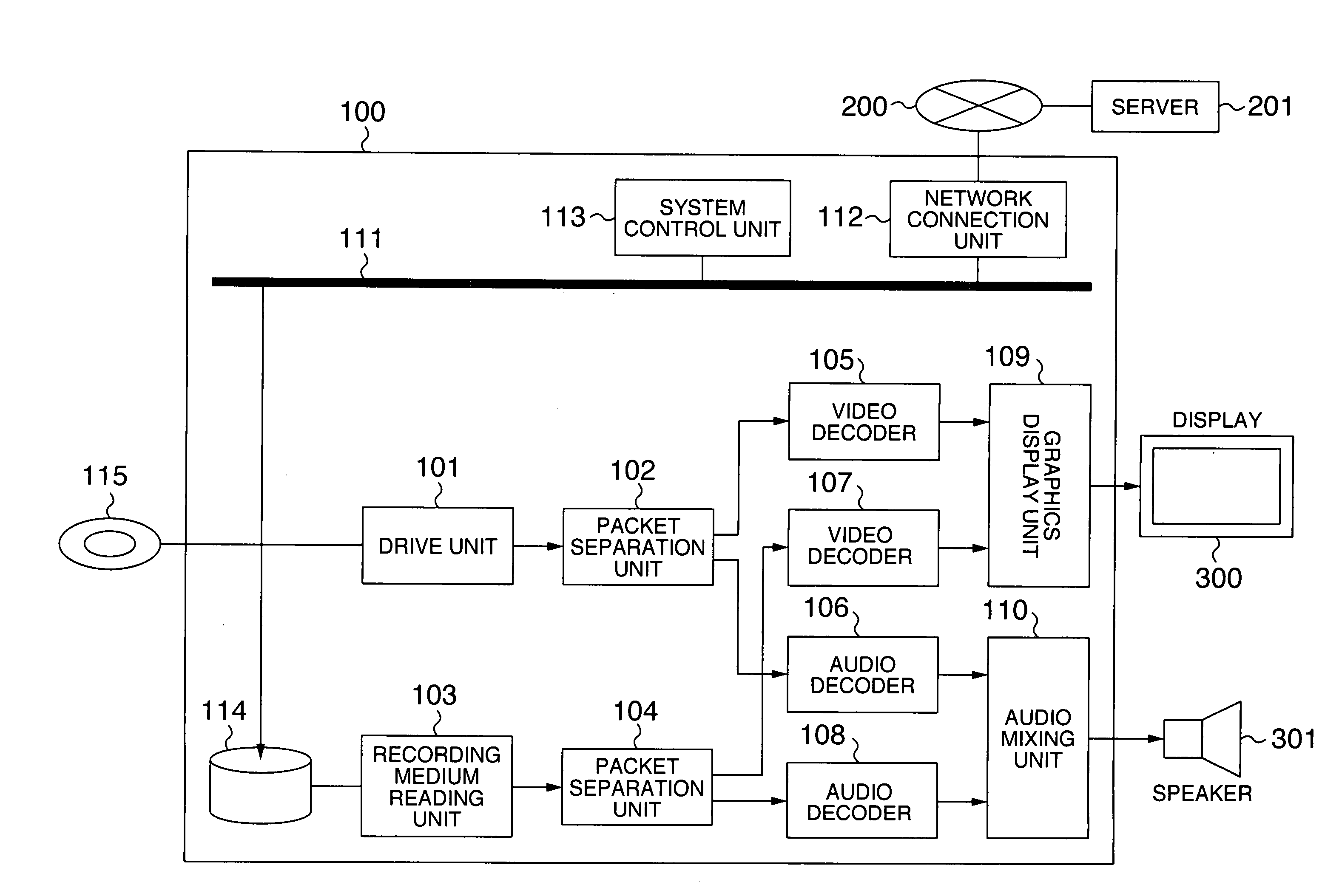
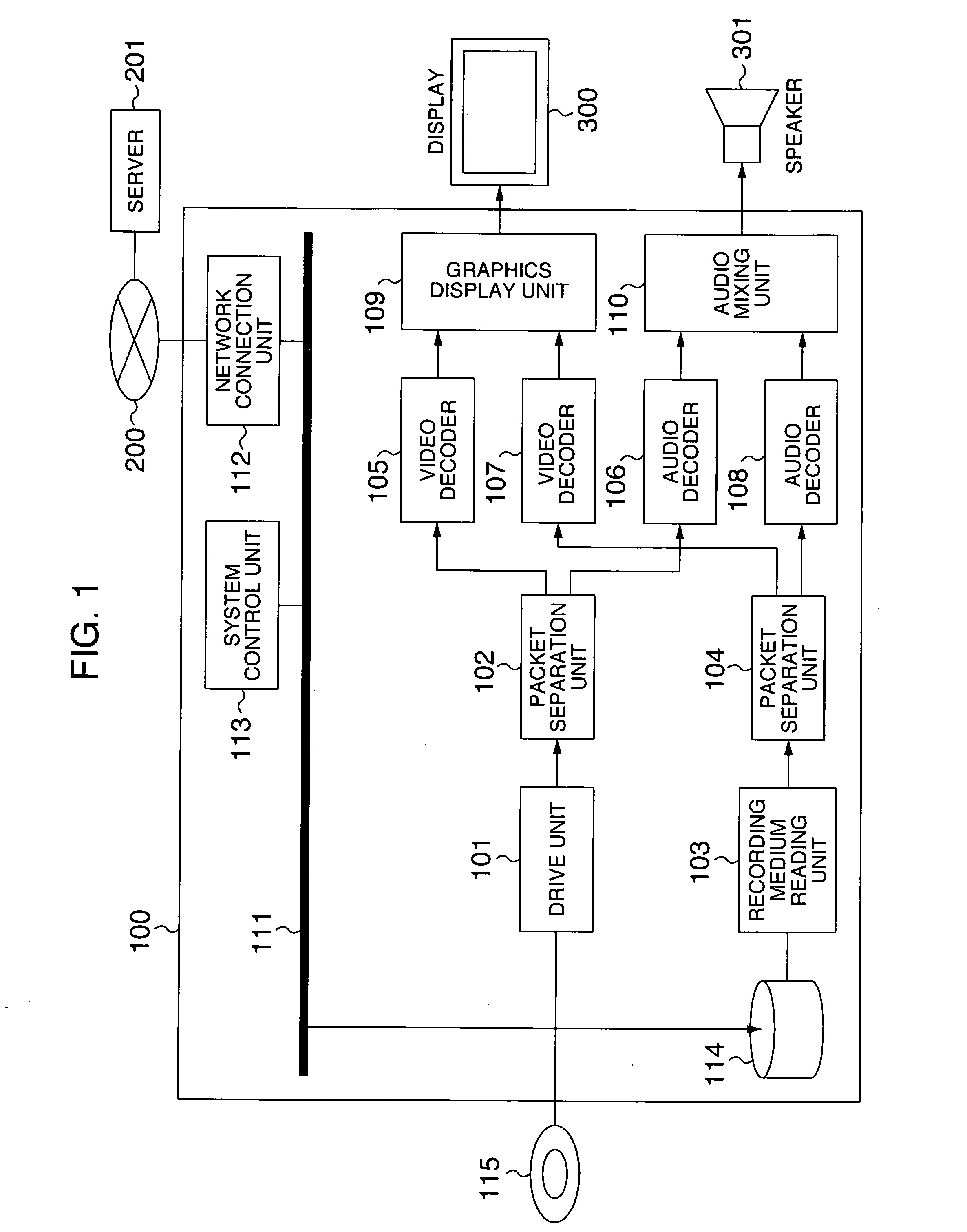
[0027]FIG. 1 illustrates a playback apparatus according to a first embodiment of the present invention. The playback apparatus 100 comprises a drive unit 101, a recording medium 114, a recording medium I / O unit 103, a first packet separation unit 102, a second packet separation unit 104, a first video decoder 105, a second video decoder 107, a first audio decoder 106, a second audio decoder 108, a graphics display unit 109, an audio mixing unit 110, a network connection unit 112, and a system control unit 113.
[0028] A description will be given of the flow of signals when a main stream is read from a disk 115, a stream for a child screen is read from a server 201 through a network 200, and they are multiplexed and outputted from a display 300 and a speaker 301. The drive unit 101 reads the stream from the disk 115, and outputs the read stream to the first packet separation unit 102. The first packet separation unit 102 separates the stream into a video stream and an audio stream. Th...
second embodiment
[0035] A second embodiment of the present invention will be described with reference to FIG. 8. Since the playback apparatus 100 is similar in configuration to the first embodiment, a description thereon is omitted. In the second embodiment, as a viewer plays back a main stream (S200), the system control unit 113 contained in the playback apparatus 100 transmits the number of times the main stream has been played back to the server 201 (S201). The server 201 has a plurality of child screen streams, and upon receipt of the number of times of playback, transmits a child screen to the playback apparatus 100 in accordance with the number of times (S203). The playback apparatus 100 superimposes the child screen stream on the main picture, and plays back the composite picture (S204).
[0036] The foregoing control permits the main stream to be composed such that video contents change each time the main stream is played back. For example, as illustrated in FIG. 9, an advertisement 503 on a b...
third embodiment
[0040] A third embodiment of the present invention will be described with reference to FIG. 10. Since the playback apparatus 100 is similar in configuration to the first embodiment, a description thereon is omitted. The third embodiment will be described in connection with a method which is utilized by a viewer when he is not willing to view part of a picture in a main stream. As illustrated in FIG. 10, when a main stream presents a quiz program, where a correct answer is displayed beforehand to viewers, some viewers do not want to know the correct answer. In this event, such viewers can cause a child screen to appear so that an area 504 is concealed. In addition, a sound may be generated together with a child screen stream in order to cancel out a sound associated with the main stream.
[0041] In the foregoing configuration, the child screen stream is retrieved from the server 201, however, in the third embodiment, the child screen stream may be stored in the disk 115 to avoid an ac...
PUM
 Abstract
Description
Claims
Application Information