[0006]The subject invention is based on the inventors' recognition that conventional spinal implants and techniques possess several shortcomings not known by those in the art. The inventors have developed not only spinal implants that are superior in their design, but also have developed a comprehensive
system for
spinal surgery, including implants that are especially adapted for an
anterior approach,
lateral approach, and the rarely implemented anterolateral
surgical approach. FIG. 33 illustrates the basic direction of access to the
intervertebral space. The
anterior approach comprises an approach directly from the anterior vector of the
vertebral body with 20 degree variability, the anterolateral approach is 45 degrees from the anterior vector with 25 degree variability and the
lateral approach is 90 degrees from the anterior vector with 20 degree variability.
Implant embodiments of the present invention facilitate easier, quicker and more precise surgical techniques that enable the restoration and re-establishment of
spinal anatomy,
lordosis and / or
disc height.
Implant embodiments of the present invention also are
safer to use and increase the chances of a positive surgical outcome.
[0008]Embodiments of the invention have an
advantage over existing implants or prostheses in that their clinical use is simplified over
current practice, resulting in shorter operative times, less risk to the patient and less cost. Embodiments described herein enable the intraoperative (intradiscal)
assembly of components of a modular implant in the
intervertebral space. In particular embodiments, implant configurations are provided that facilitate intraoperative
assembly for implementation for the anterior, anterolateral and lateral surgical approaches. In certain embodiments, the components are configured such that they are sectioned and associate along a
longitudinal plane, as illustrated in FIGS. 33 to 36. FIGS. 33 to 35 show that the
modularity of the implants may be defined along a
coronal plane CLP, which is particularly advantageous for anterior or lateral surgical approaches; and a
transverse plane TP, which is particularly advantageous for an anterolateral
surgical approach. Unless specifically stated otherwise, use of the term “
longitudinal plane” to describe
modularity of embodiments of the invention refers to sectioning along a coronal or
transverse plane or a plane having at least a coronal or transverse aspect thereto.
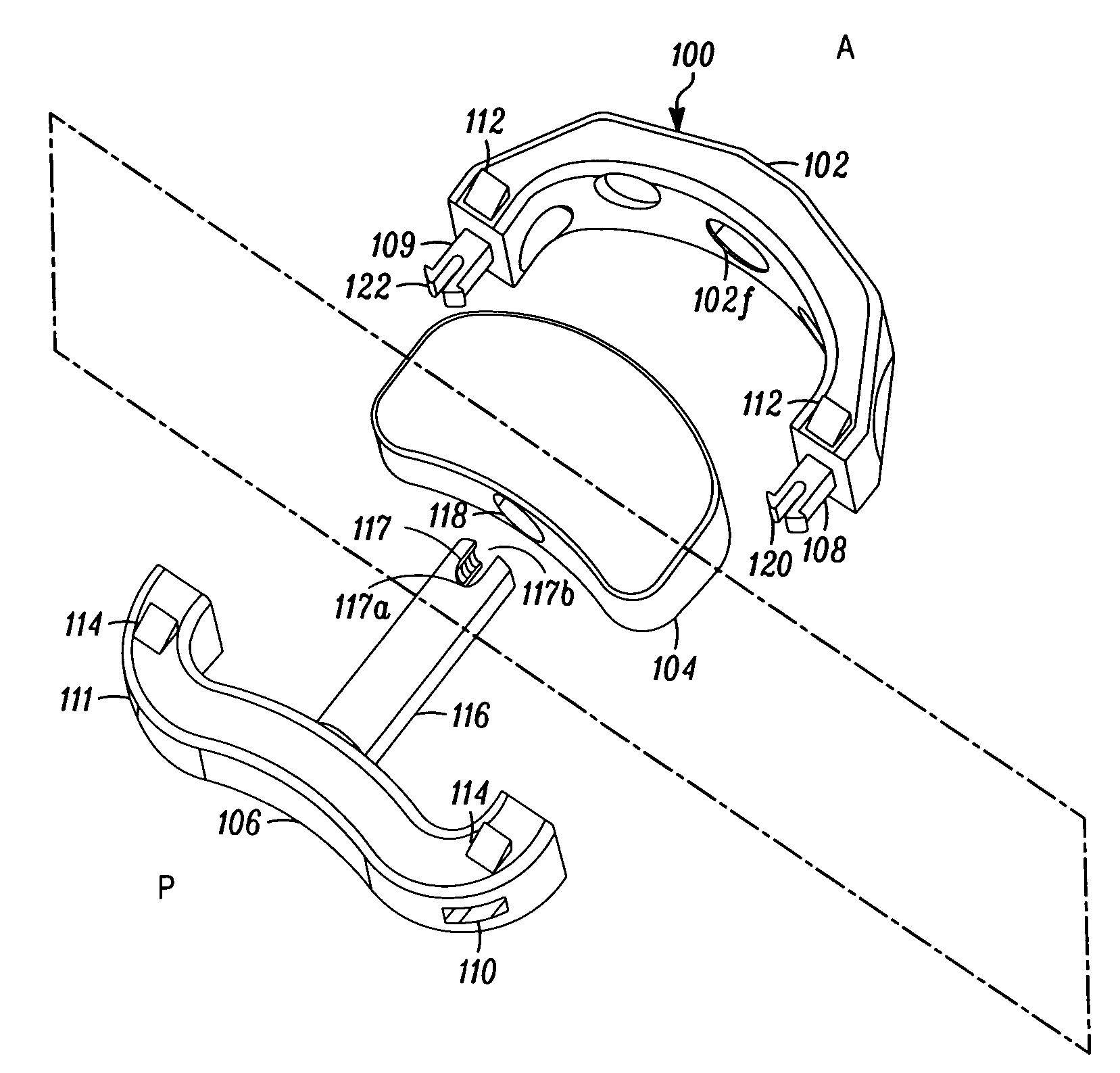
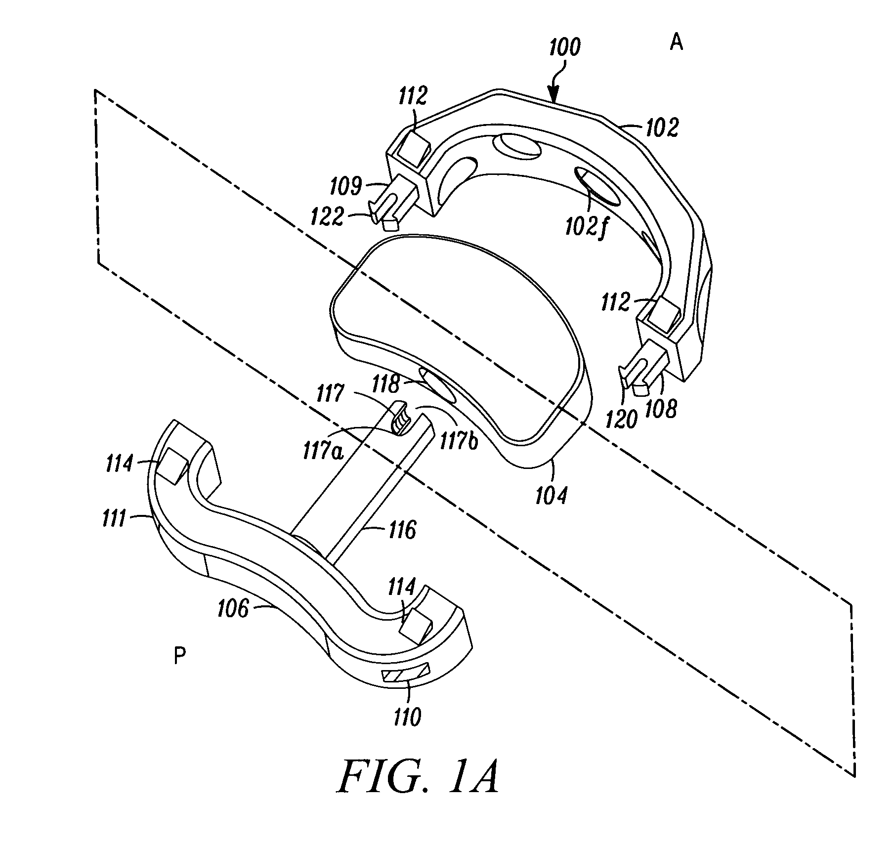
[0009]In a specific embodiment, a first component is surgically placed into the
intervertebral space at a predominantly posterior position then a second component is placed in a predominantly anterior position of the intervertebral space. Typically, this will be performed following measurement with trial spacers. The ability to first position a component posteriorly and then anteriorly enables the surgeon to intraoperatively optimize the size and slope of the implant for a patient's given anatomical size. This avoids the need for an unnecessarily large amount of different single piece sizes. The embodiment also accomodates a broad range of different space sizes and unique patient
anatomy with a manageable set of component sizes. Furthermore, the placement of a predominantly posterior component followed by a predominantly anterior component facilitates the adjustment of
lordosis as a function of the first component having a first size and dimension that serves as an initial support and forms the desired angle and space for placement of the second component having different size and dimension. Embodiments of the present invention are sectioned and configured to increase ease of
insertion into the intervertebral space for each of the surgical approaches (anterior, anterolateral and lateral) while facilitating the interdiscal
assembly of the implant. While the implant embodiments enable intraoperative assembly, those skilled in the art will appreciate that presurgical assembly of the components may be conducted dependent on the surgeon's preference.
[0010]Another problem recognized by the inventors involves the way that conventional implants interact with
bone surface of the
vertebral body. Many conventional implants with single piece or modular arrangement fail to take into account the natural
anatomy of the interior surface of the
vertebral body. The inventors are of the belief that maximizing the surface between the implant and vertebral body will improve the surgical result. Accordingly, in another embodiment, both the first and the second components comprise geometric dimensions that serve to restore
anatomy, proper
lordosis and / or
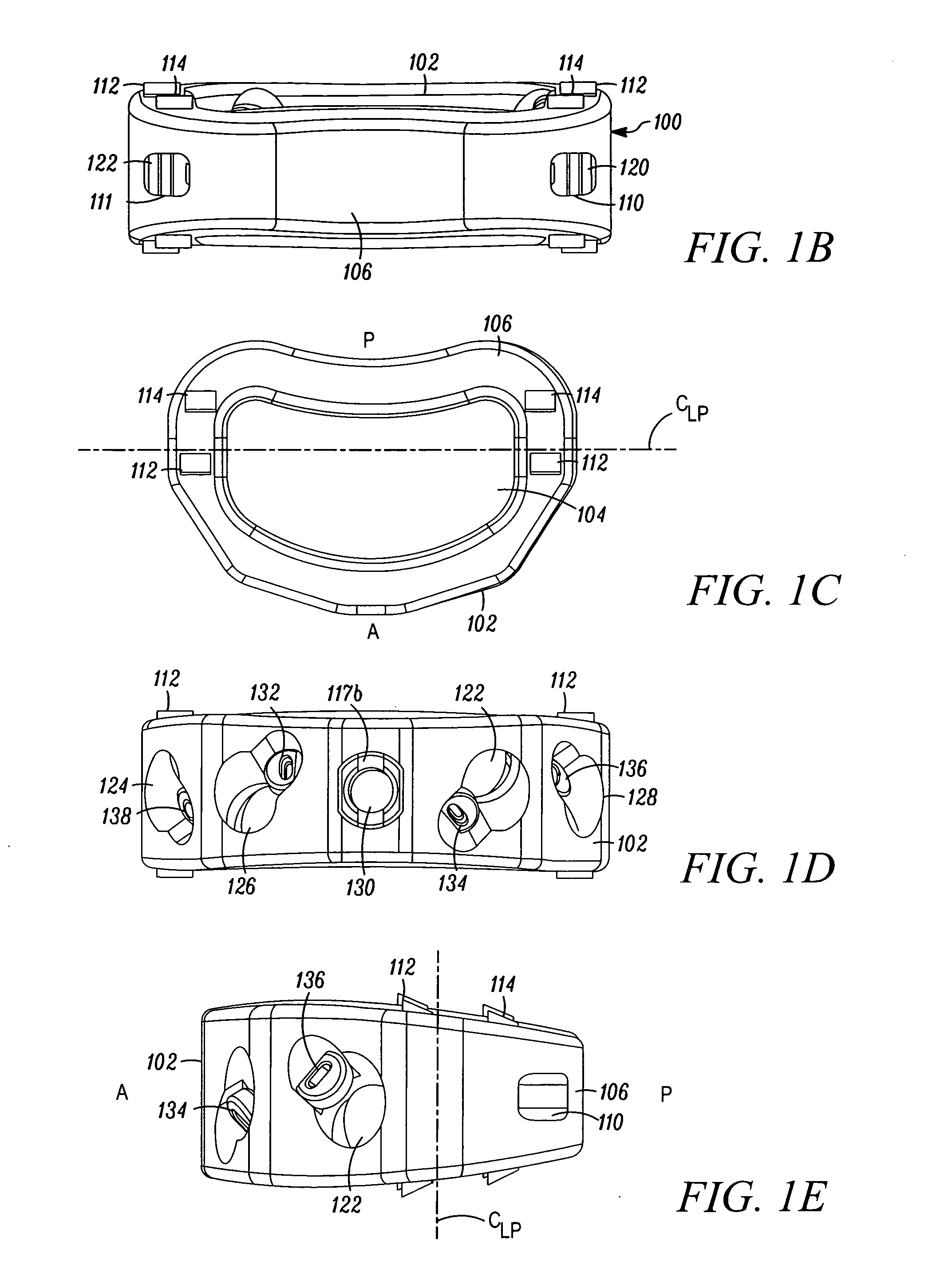
disc height. In a particular embodiment, the individual components are assembled together to form a unitary implant that has a tapered convex shape in a sagital plane and may also be an elliptical shape in a
coronal plane. This is an advantageous feature of the embodiments because, unlike conventional modular implants that lack a coordination of the components to form a
geometric configuration mirroring the intervertebral space, the components of this embodiment increase implant / bone
load bearing surface area, restore natural anatomy of the disc and establish a desired space height and a desired lordosis.
[0012]Another problem that the inventors have recognized with conventional implants is an absence of variability in the vector that the bone fixator (screw) may be directed for securement to the vertebral bodies relative to the angle of the implant. For example, the '464 patent described above discloses a number of boreholes through which the fixators are directed through (in this example secured to the boreholes via threads) such as described in FIG. 28. However, the vector of the fixator is static. That is, the bone screw cannot move relative to the vector of the borehole. The inventors have recognized that this is a shortcoming in conventional design. Adjacent to the
spinal column is critical vasculature for the body which runs down along the anterior portion of the spine. Further, the spinal nerves extend out laterally from the spine. Thus, a challenge for spinal surgeons is avoiding such vital
anatomical structures during
surgery as well as securing the implant so as to minimize possible interference between the implant or fixators and the vital
anatomical structures subsequent to
surgery. Accordingly, another implant embodiment comprises channels that allow for angular variability in the vector of the fixator is desired. FIG. 31 illustrates the angular variability or dynamism of the fixator allowed by the channel. This angular variability now provides surgeons with a level of adjustability with respect to where the fixators are secured and the orientation and placement of the implant relative to the fixators. This in turn will enable the surgeon to place the fixators in such a way as to minimize disrupting or damaging vasculature and nerves, whether intraoperatively or post-operatively, as well as adapt to a patient's unique anatomy. Increased safety and improved surgical outcomes are achieved.
[0026]It is an
advantage that the practitioner can select an appropriate size of components from the kit of parts to suit the particular size and shape of the space into which the implant or
prosthesis is to be inserted. Not only do sizes vary from patient to patient, but also the size and shape of the space varies according to the location in the spine. Accordingly, depending on the size and / or shape of a intervertebral space, a practioner can choose a first component, such as an anterior component, having a certain size and / or dimension, and a second component, such a posterior component, having a certain size and / or dimension, to customize the overall size and shape of the unitary implant to produce an implant particularly suitable for the surgical space.

