Device for use in the eye

a technology for eye devices and eyelids, applied in eye surgery, eye treatment, suction devices, etc., can solve the problems of excessive drainage, early postoperative hypotony, poor control of flow through,

Inactive Publication Date: 2001-02-13
UNIV COLLEGE LONDON INST OF OPHTHALMOLOGY +1
View PDF1 Cites 327 Cited by
  • Summary
  • Abstract
  • Description
  • Claims
  • Application Information

AI Technical Summary

Problems solved by technology

Current GFIs are commonly associated with excessive drainage and early postoperative hypotony.
This results from either poor control over flow through the GFI, uncontrolled external leakage of fluid between the GFI and the walls of the GFS channel into which it is inserted, or both poor internal flow control and external leakage.
Whilst some control is available by providing implants having different plate areas, this is inadequate in many circumstances.
Whilst this provides some improvement to control of flow resistance, this is still inadequate in some circumstances.
One problem with both the original and dual ridge Molteno devices and the Baerveldt device is that the flow resistance is very dependent upon suture tension.
For all of the devices the eventual IOP can be too low for safety and all are subject to progressive fibrous obliteration by continued subconjunctival wound healing processes after surgery, which may result in eventual filtration failure.
One problem with at least the Krupin device is that of hysteresis, that is that the valve clo

Method used


Image

  • Device for use in the eye
  • Device for use in the eye
  • Device for use in the eye

Examples


Embodiment Construction

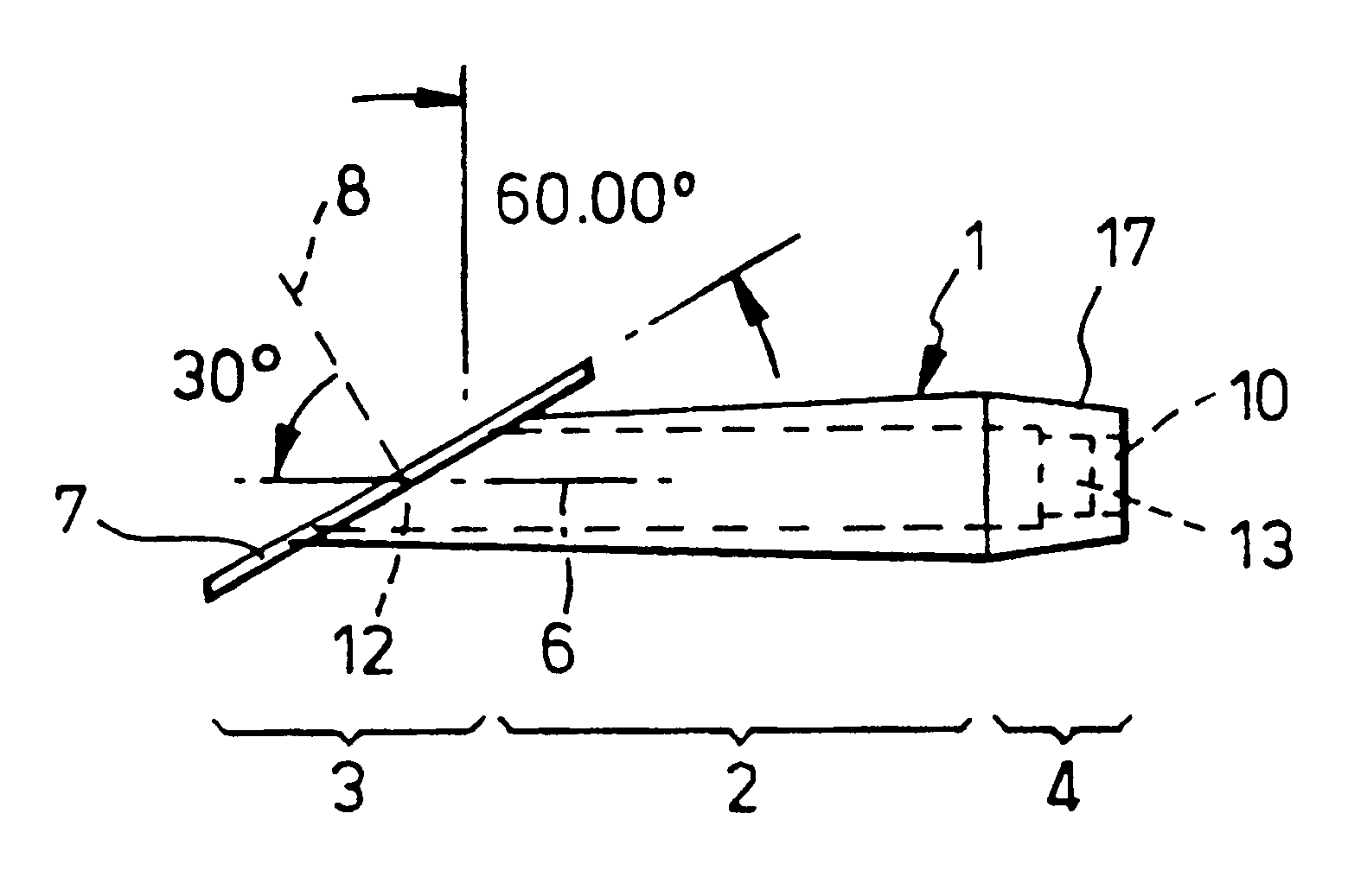
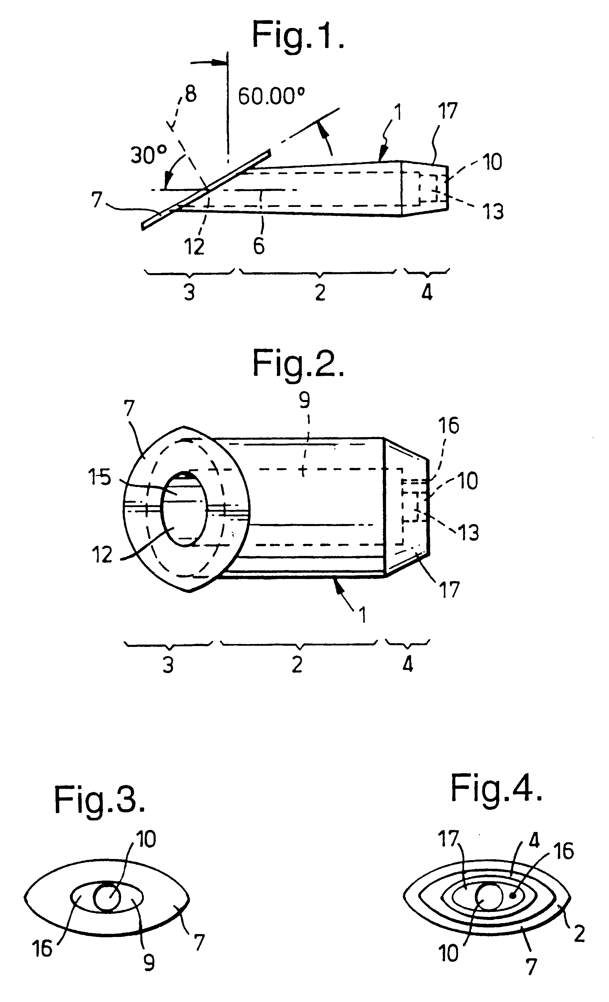
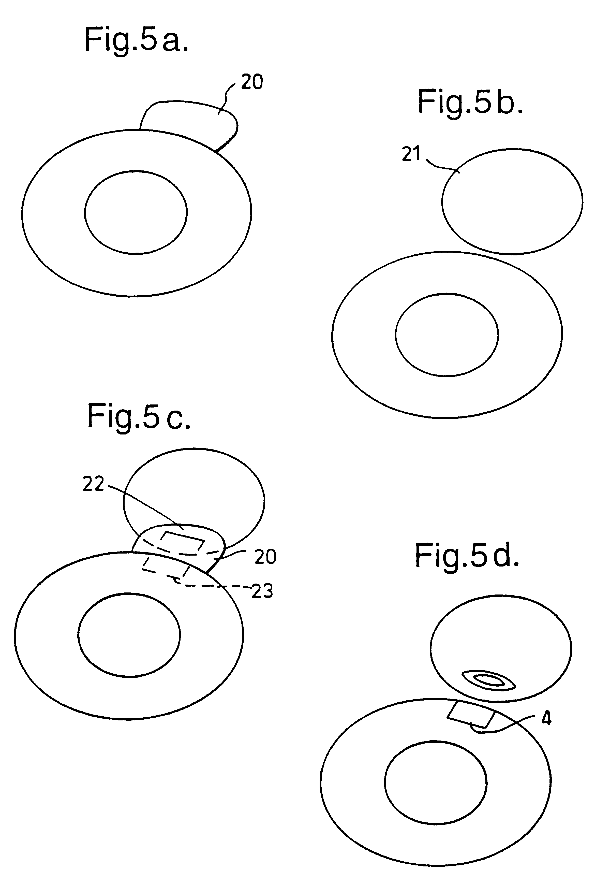
The present inventor determines that it would be desirable for a device to be provided which allows a predetermined flow rate of intraocular fluid through the device whilst minimising flow through the incision around the outside of the device and preferably allows for adjustment of the flow rate after implantation.

A new device according to the invention for positioning in a slit aperture in the eye of a human or animal patient for relieving glaucoma comprises an elongate body section, interior and exterior end sections at the respective interior and exterior ends of the body section, and at least one lumen extending through the body between the interior and exterior ends thereof, and the exterior end section preferably has a channel one end of which has a mouth which opens to the outside of the device (i.e. in said other cavity) and the other end of which is in fluid communication with at least one of the said at least one lumen, the interior end section has a passageway one end of ...


PUM

PropertyMeasurementUnit
Luminous fluxaaaaaaaaaa
Pressureaaaaaaaaaa
Angleaaaaaaaaaa

Abstract

A glaucoma filtration implant is constituted by a generally tubular body section having an oblong external diameter formed of a continuous convex curve. The device preferably has flow resistance structure provided by a portion of the internal lumen having a reduced diameter. The flow resistance structure may have a length of up to 5000 mum and a diameter in the range 15 to 50 mum, the diameter being selected so as to achieve a pressure drop along the flow resistance structure in the range 5 to 15 mm Hg. The internal conduit for liquid flow also may include a removable flow inhibitor, which can be removed after implantation by a laser, such as an ophthalmic YAG laser. The device is made of biocompatible materials.

Description

The present invention relates to a device for insertion in the eye, specifically to a drainage implant for a glaucoma patient, and to a method for using such a device.Glaucoma is a common cause of blindness or visual impairment throughout the world, affecting about 1 person in 40 at some point in their life to a varying degree. In glaucoma, the fluid drainage pathways from the eye become restricted or damaged. As a result, fluid pressure within the eye (the intra-ocular fluid pressure, IOP) rises and the optic nerve is damaged by the raised fluid pressure.Medical treatment, typically by the application of eye drops containing drugs which either decrease intraocular fluid production or increase outflow, requires lifelong compliance which is only infrequently attained in practice. Medical treatment is often only partially successful in retarding disease progression, with continued optic nerve damage and visual field loss.The alternative is glaucoma drainage or filtration surgery (GFS)...

Claims


Application Information

Patent Timeline
IPC IPC(8): A61F9/007C08F230/08C08F220/58C08F230/00C08F220/00
CPCA61F9/00781C08F220/58C08F230/08
Inventor ALLAN, BRUCE DUNCAN SAMUELMUIR, ANDREW VICTOR GRAHAMJONES, STEPHEN ALISTER
Owner UNIV COLLEGE LONDON INST OF OPHTHALMOLOGY
Why Eureka
Try Eureka