Hearing aid system

a technology of hearing aids and auxiliary devices, applied in the field of hearing aid systems, can solve the problems of skin infections, patients often complain about poor esthetics, significant drawbacks for patients, etc., and achieve the effects of reducing the force of magnetic attachment, and facilitating chang

Inactive Publication Date: 2007-03-08
OTICON
View PDF11 Cites 212 Cited by
  • Summary
  • Abstract
  • Description
  • Claims
  • Application Information

AI Technical Summary

Benefits of technology

[0021] In a preferred embodiment of the present invention, the skin contact pressure plate has a coupling at a lateral side of the skin contact pressure plate. In that way the skin contact pressure plate may be easily changed and may be individually fitted for each patient in terms of for example magnet strength and size of the skin contact pressure plate.
[0022] In a preferred embodiment of the present invention, the skin contact pressure plate has a skin contact spacer at its contra lateral end and the skin contact spacer has a coupling to the skin contact pressure plate. This skin contact spacer serves to reduce the force of the magnetic attachment between the external hearing aid unit and the implanted unit.
[0023] For a patient with quite thick skin between the implanted unit and the skin contact pressure plate, no skin contact spacer might be needed. However, for a patient with quite thin skin in this area, a skin contact spacer might be useful to reduce the magnetic attachment force. The skin contact spacer may be of plastic and may increase the distance between the magnetic portion of the skin contact pressure plate and the skin of the patient.

Problems solved by technology

However, they all include significant drawbacks for the patient, as described below.
For the traditional bone conductors with a spring arrangement around the head the constant pressure against the skull bone often causes headaches and the patients often complain about the poor esthetics.
If this type of bone conductor is designed with a permanent skin penetration patients often have problems with skin infections.
If this type of bone conductor is instead designed with a fully implanted vibrator there is a significant energy loss when transmitting the energy with an inductive link through the skin and another drawback is that the vibrator can not easily be repaired if it breaks down.
If the skin would be surgically prepared so that it becomes very thin this would lead to skin necrosis due to poor blood supply in the compressed skin so this type of device does not work well.

Method used


Image

  • Hearing aid system
  • Hearing aid system
  • Hearing aid system

Examples


Embodiment Construction

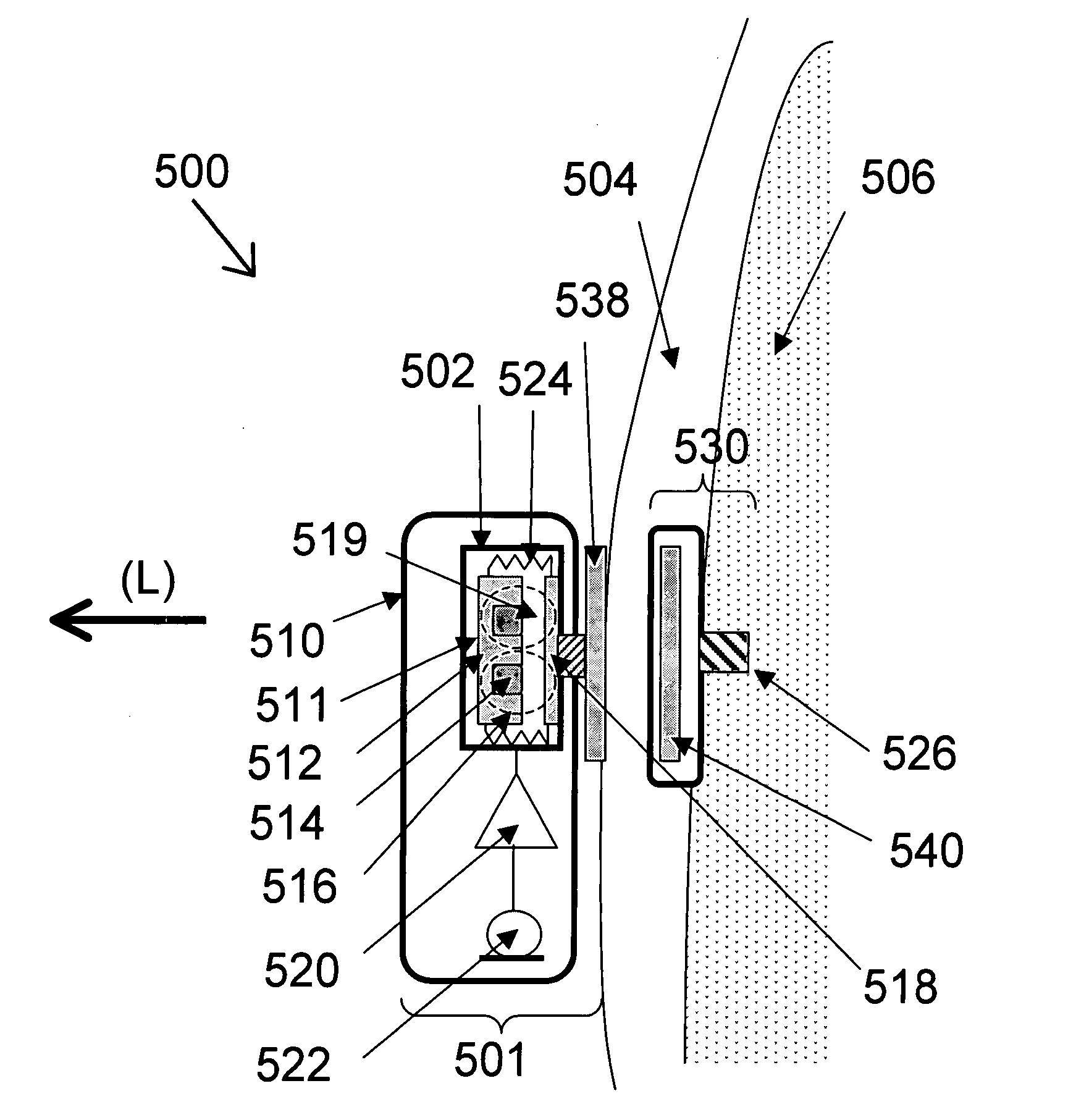
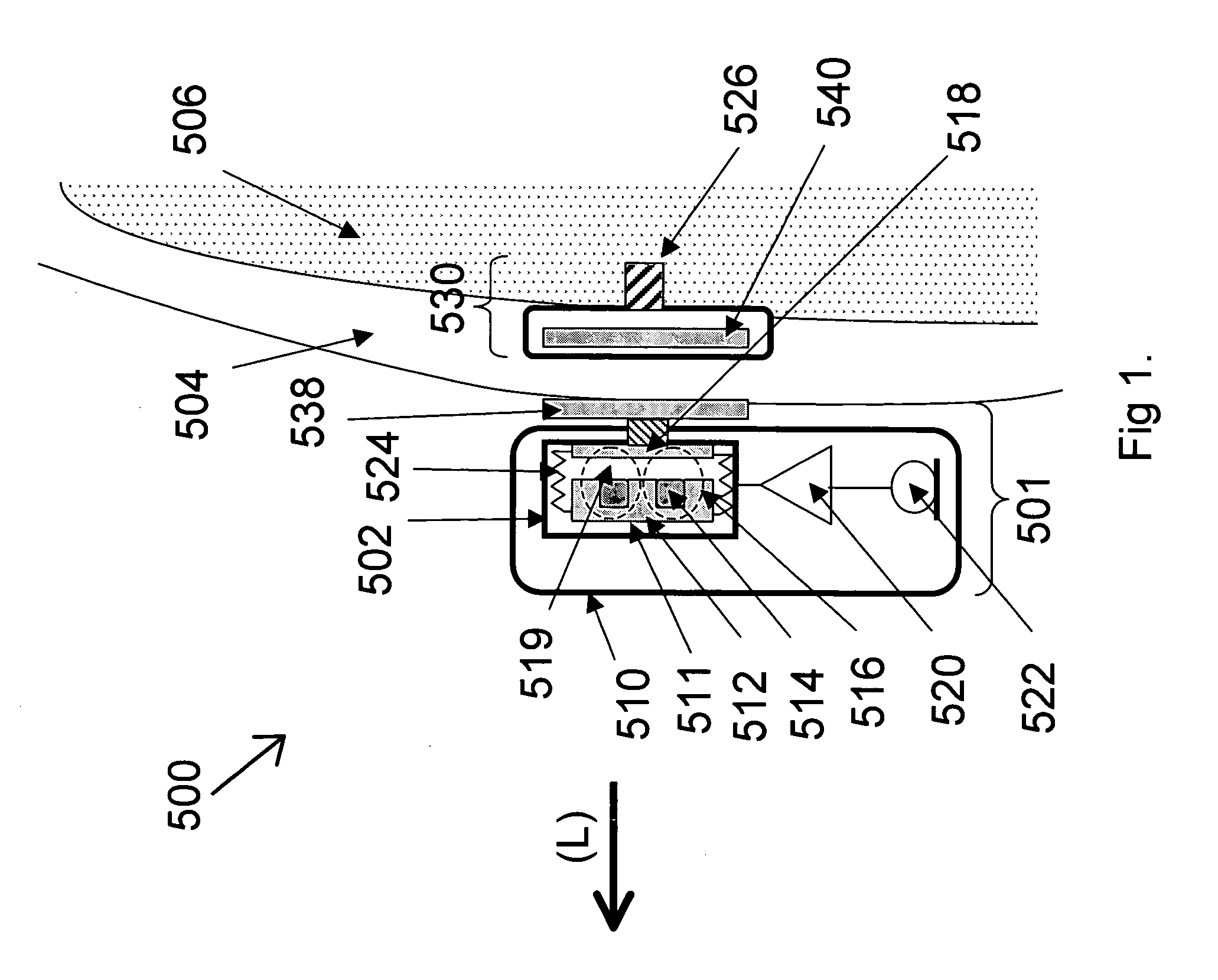
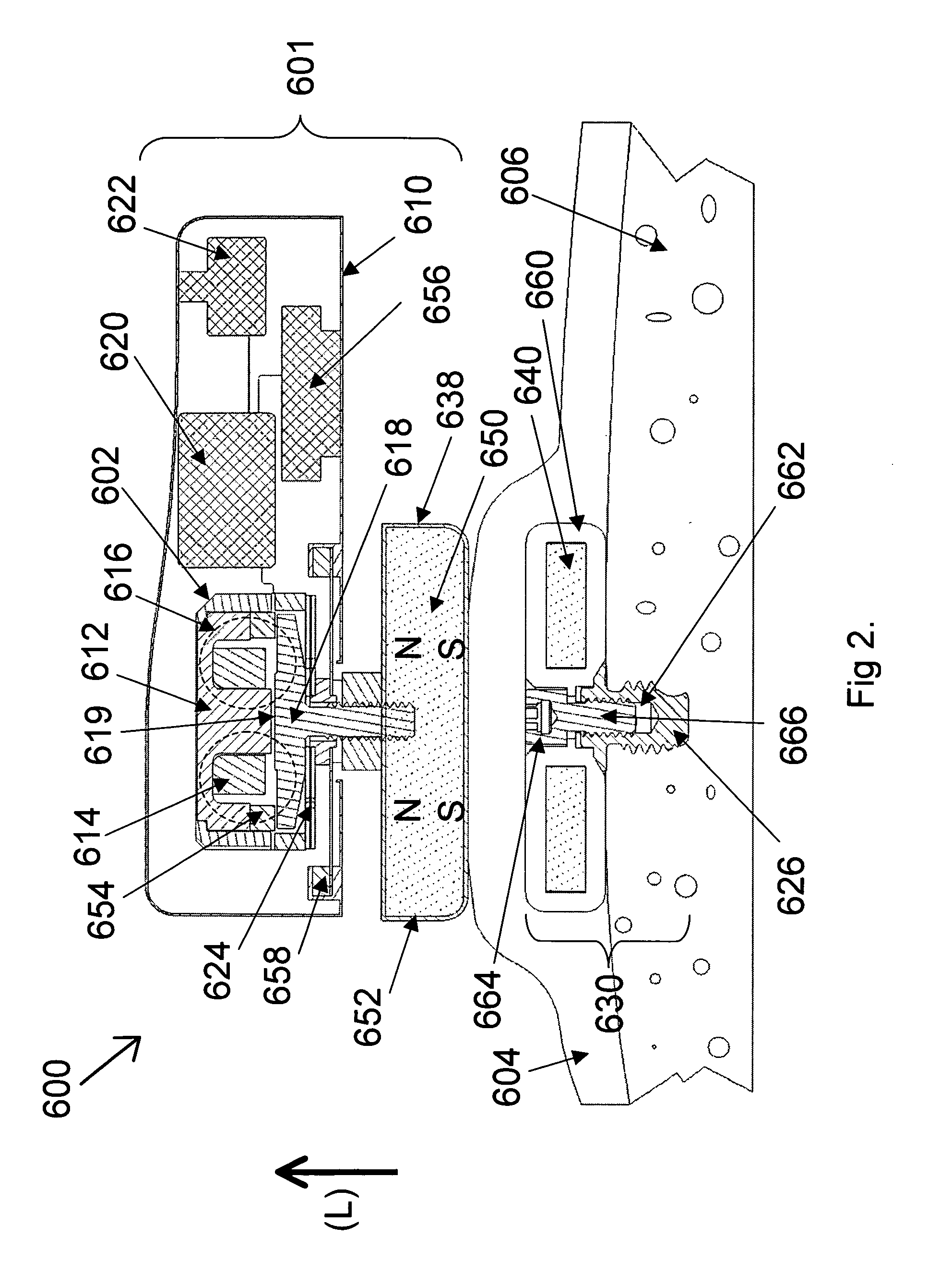
[0030]FIG. 1 is a cross-sectional side-view of the hearing aid system 500 of the present invention. An external hearing aid unit 501 has a vibrator 502 disposed therein. The vibrator 502 may be an assembled integrated unit so that all vibrator components may be disposed inside the external hearing aid unit 501. Preferably, the vibrator 502 has a vibrator plate 518 that is connected to a skin contact pressure plate 538 via a connector segment. The skin contact pressure plate 538 is magnetic so that it is magnetically attracted to a magnetic portion 540 of an implanted unit 530 that is anchored in the skull bone 506 by a fixation portion 526. This magnetic interaction presses the skin contact pressure plate 538 against the skin 504. The vibrations from the integrated vibrator 502 are transmitted to the skin contact pressure plate 538 and then through the skin 504 of the skull bone 506 to the implanted unit 530. It is also possible to make the skin contact pressure plate 538 of a suita...


PUM


Abstract

A bone conduction hearing aid system for generating bone conduction vibrations is disclosed. The bone conduction hearing aid system has an external hearing aid unit with a vibrator and a skin contact pressure plate. The skin contact pressure plate is placed on an outside of the external hearing aid unit and the skin contact pressure plate is magnetically attached to an implanted unit anchored to the skull under the skin. The vibrator transforms an electrical signal into mechanical vibrations and the skin contact pressure plate allows transmission of the vibrations from the vibrator to the implanted unit when the external hearing aid unit is magnetically fixed to the implanted unit.

Description

TECHNICAL FIELD [0001] The present invention relates to a hearing aid system for providing bone conduction hearing. BACKGROUND OF THE INVENTION [0002] Bone conduction is the principle of transmitting vibrations via the skull bone to the inner ear, i.e. the cochlea. Several different types of bone conduction hearing aids are available. However, they all include significant drawbacks for the patient, as described below. [0003] The traditional bone conductor consists of a hearing aid with a vibrator that is pressed against the head behind the ear by a spring arrangement extending from the other side of the head. The steel spring arrangement is sometimes built into an eyeglass frame. The vibrations are then transmitted through the skin and the skull bone into the cochlea. For the traditional bone conductors with a spring arrangement around the head the constant pressure against the skull bone often causes headaches and the patients often complain about the poor esthetics. [0004] Another...

Claims


Application Information

Patent Timeline
Patent Type & Authority Applications(United States)
IPC IPC(8): H04R25/00
CPCH04R2460/13H04R25/606
Inventor WESTERKULL, PATRIK
Owner OTICON
Why Eureka
Try Eureka