Antenna apparatus

a technology of antenna apparatus and antenna, which is applied in the direction of antennas, antenna details, antenna feed intermediates, etc., can solve the problems of deterioration of communication quality or communication failure, difficult to resolve radio dead zones in all directions, etc., and achieves the effect of suppressing the change of an antenna directivity pattern and improving the voltage standing wave ratio (vswr)

Inactive Publication Date: 2010-10-12
SAMSUNG ELECTRONICS CO LTD
View PDF17 Cites 217 Cited by
  • Summary
  • Abstract
  • Description
  • Claims
  • Application Information

AI Technical Summary

Benefits of technology

[0008]The present invention has been made to solve the above-mentioned problems occurring in the prior art, and the present invention provides an antenna apparatus, which removes dead directions, and at the same time, has a suppression means for easily suppressing the change of an antenna directivity pattern caused by the effect of a feed line or a radome and an improvement means for simply improving the Voltage Standing Wave Ratio (VSWR) deterioration caused by the effect of a reflector or the radome.

Problems solved by technology

This attenuation causes the deterioration of communication quality or communication failure, which makes it difficult to resolve the radio dead zones throughout all directions.

Method used


Image

  • Antenna apparatus
  • Antenna apparatus
  • Antenna apparatus

Examples


Embodiment Construction

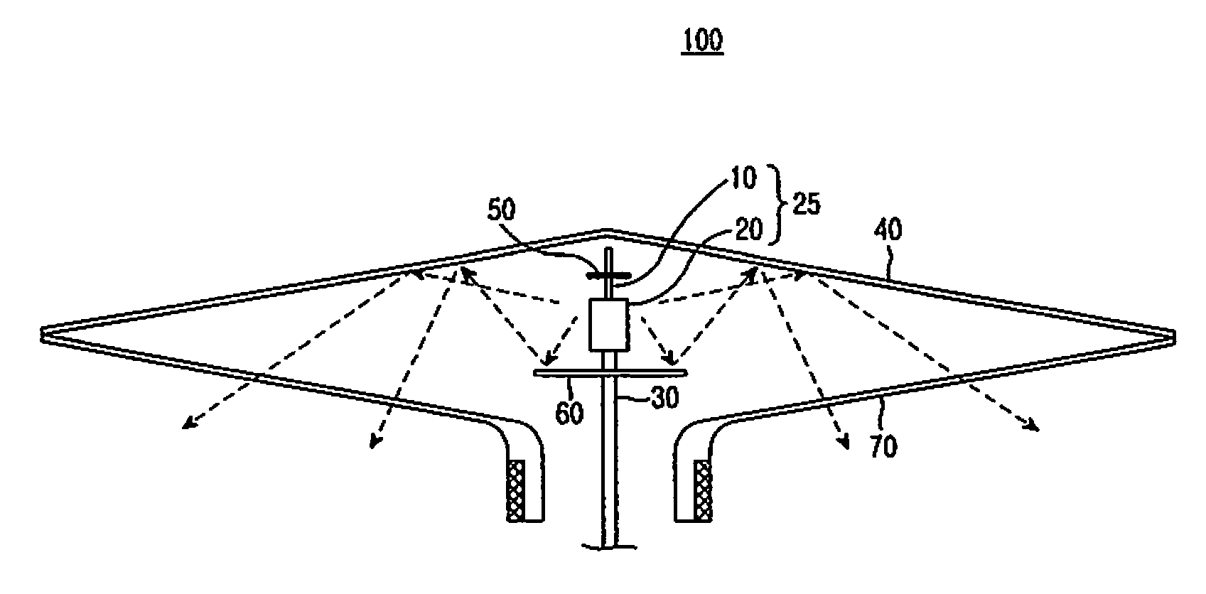
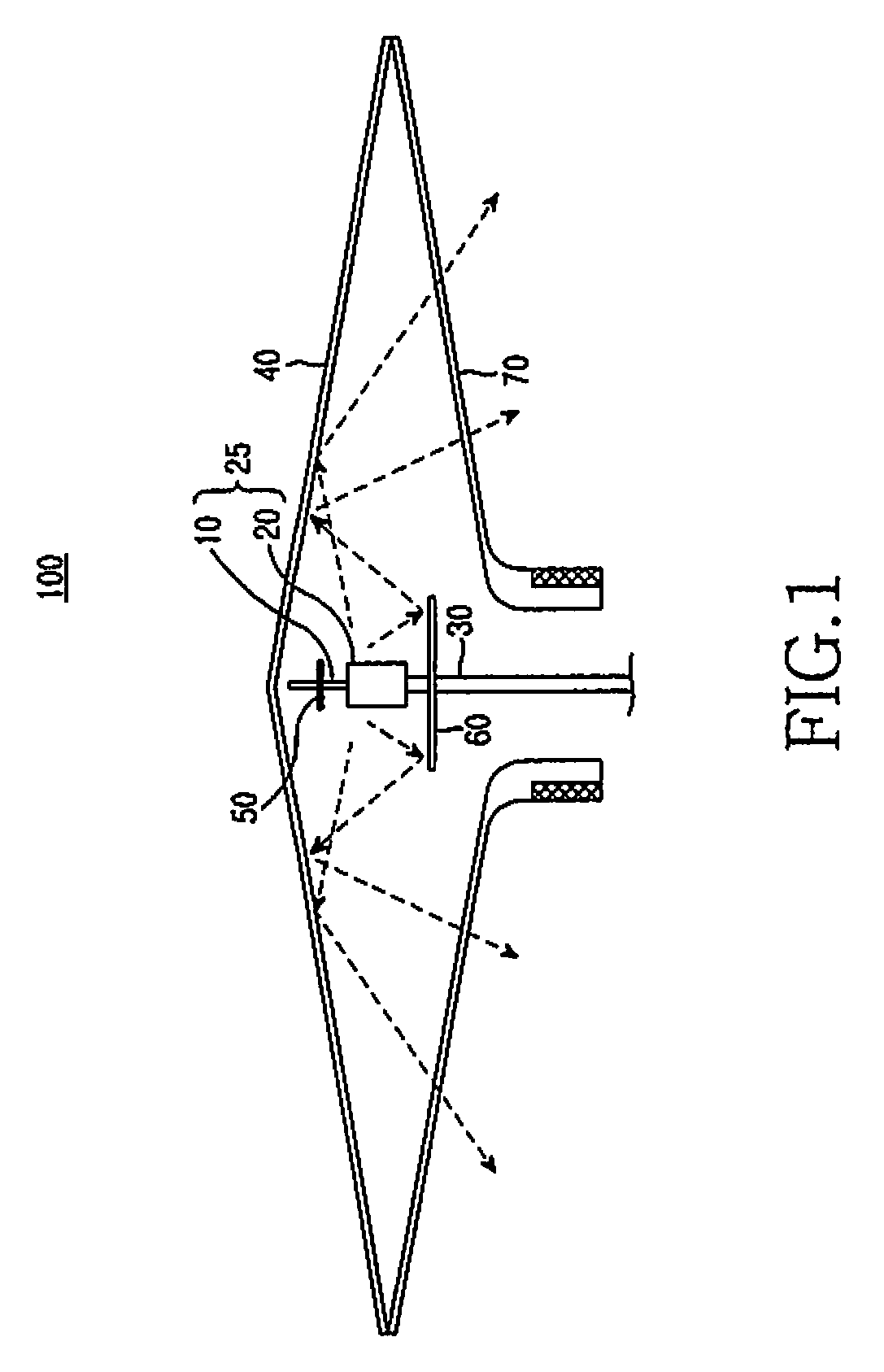
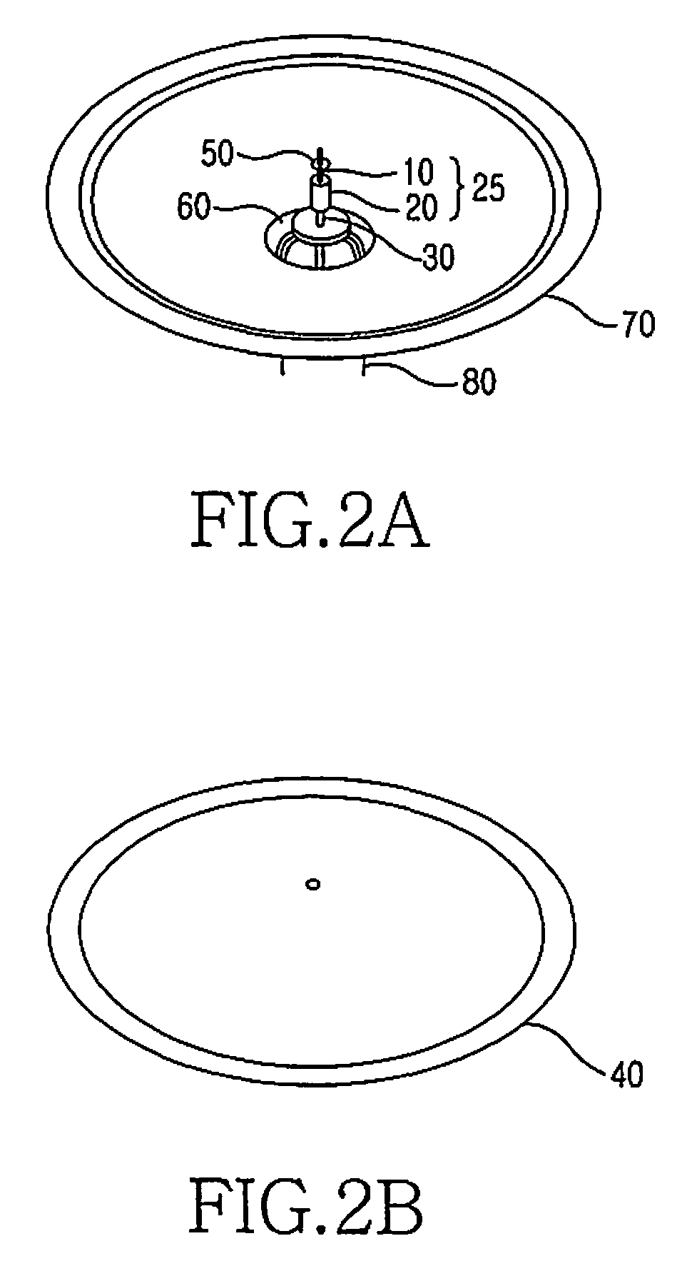
[0024]FIG. 1 is a view of an antenna configuration of an antenna apparatus of the present invention. A sleeve antenna 25 includes a central conductor 10 connected to a coaxial cable 30 supplied with RF power of radiation radio waves and a sleeve 20. Also, the antenna apparatus 100 includes the sleeve antenna 25, a reflector 40 in the shape of a cone, and a resinoid radome 70 in the shape of a cone, in which the sleeve antenna 25 is housed within a housing space formed by closely approaching a lower surface of the reflector 40 and a lower surface of the radome 70 to each other. The sleeve antenna 25 is arranged in a concave portion of the reflector 40 in such a manner that the central conductor 10 is aligned with the central axis of the cone and a top end of the central conductor 10 is separate from a vertex of the cone.

[0025]In addition, the antenna apparatus 100 includes, at the top end portion of the central conductor 10, an impedance matching disk 50 for improving VSWR deteriorat...


PUM


Abstract

An antenna apparatus is provided, which removes dead directions, and at the same time, has a suppression means for easily suppressing the change of an antenna directivity pattern caused by the effect of a feed line or a radome and an improvement means for simply improving the VSWR deterioration caused by the effect of a reflector or the radome. The antenna apparatus includes a sleeve antenna connected to a coaxial cable and a reflector in the shape of a cone, the sleeve antenna including a central conductor and a sleeve, in which the sleeve antenna is arranged in a concave portion of the cone so that the central conductor is aligned with a central axis of the cone, and a top end of the central conductor is separate from a vertex portion of the cone.

Description

PRIORITY[0001]This application claims priority under 35 U.S.C. §119(a) to an application entitled “Antenna Apparatus” filed in the Japanese Patent Office on Dec. 26, 2006 and assigned Serial No. 350034 / 2006, and filed in the Korean Intellectual Property Office on May 29, 2007 and assigned Serial No. 2007-52289, the contents of which are hereby incorporated by reference.BACKGROUND OF THE INVENTION[0002]1. Field of the Invention[0003]The present invention relates to an antenna for a base station of mobile communication system, and in particular, to an antenna apparatus for a base station suitable for narrow service areas, or to an antenna apparatus for a relay station in dead zones.[0004]2. Description of the Related Art[0005]Antennas for the base stations of mobile communication systems are classified into base station antennas for the purpose of covering large-scale regions and base station antennas for the purpose of covering relatively limited, small-scale regions. The antennas fo...

Claims


Application Information

Patent Timeline
Patent Type & Authority Patents(United States)
IPC IPC(8): H01Q9/04
CPCH01Q1/246H01Q1/42H01Q9/16H01Q9/30H01Q19/023H01Q19/102
Inventor HASEGAWA, MINORU
Owner SAMSUNG ELECTRONICS CO LTD
Why Eureka
Try Eureka