Apparatus and Method for Recovering Carbon Dioxide from Flue Gas Using Ammonia Water

a technology of ammonia water and carbon dioxide, which is applied in the direction of liquid degasification, separation processes, and emission prevention. it can solve the problems of increasing treatment costs, increasing the concentration of ammonia in the regeneration column, and clogging of the absorption column and the regeneration column, so as to prevent the volatilization of ammonia and reduce the temperature of the absorbent , the effect of increasing the absorption efficiency of carbon dioxid

Active Publication Date: 2008-12-18
RES INST OF IND SCI & TECH
View PDF13 Cites 104 Cited by
  • Summary
  • Abstract
  • Description
  • Claims
  • Application Information

AI Technical Summary

Benefits of technology

[0015]Accordingly, the present invention has been made keeping in mind the above problems occurring in the related art, and provides an apparatus for recovering carbon dioxide from flue gas using ammonia water, in which a high-temperature absorbent is circulated o

Problems solved by technology

However, the case where the amine-based compound is used as the absorbent suffers because the amine-based compound is expensive, undesirably increasing treatment costs, and also, because a mechanical system for absorbing and separating carbon dioxide from flue gas is corroded by the amine-based compound, undesirably requiring maintenance.
As well, although problems related to the loss of ammonia are solved by providing each of the absorption column and the regeneration column with an additional washing column to recover ammonia therefrom, ammonia partially reacts with carbon dioxide to thus produce ammonia salt at low temperatures, thereby causing line clogging problems in the absorption column and the regeneration column.
This ammonia is concentrated again in a concentration column, but ammonia thus concentrated is introduced into the lower portion of the regeneration column, and thus the concentration of ammonia is difficult to maintain uniform in the regeneration column.
Accordingly, the case where a reboiling process is performed in the regeneration column is problematic in that a lot of energy must be supplied.
When the temperature is increased

Method used


Image

  • Apparatus and Method for Recovering Carbon Dioxide from Flue Gas Using Ammonia Water
  • Apparatus and Method for Recovering Carbon Dioxide from Flue Gas Using Ammonia Water
  • Apparatus and Method for Recovering Carbon Dioxide from Flue Gas Using Ammonia Water

Examples


example 1

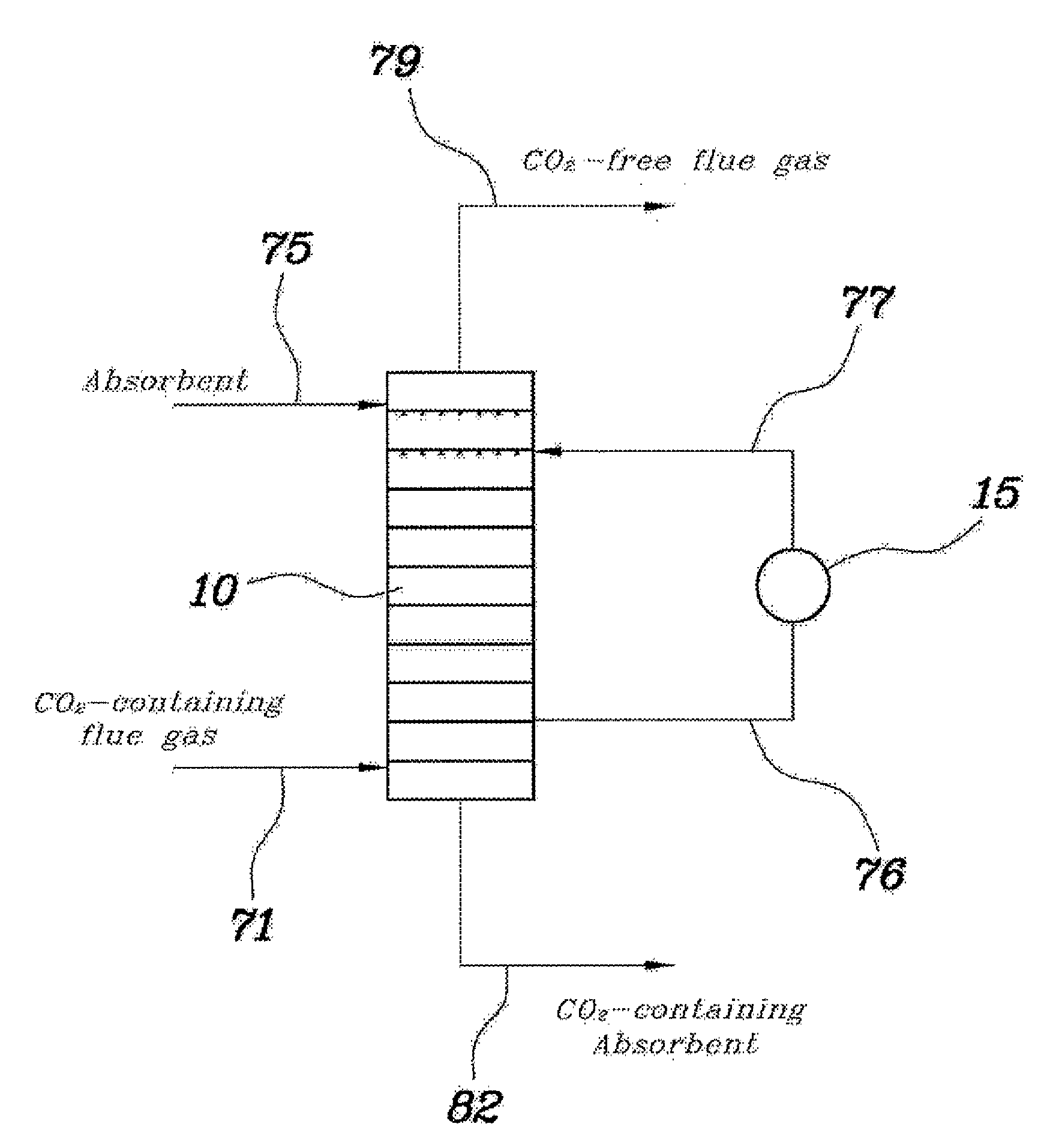
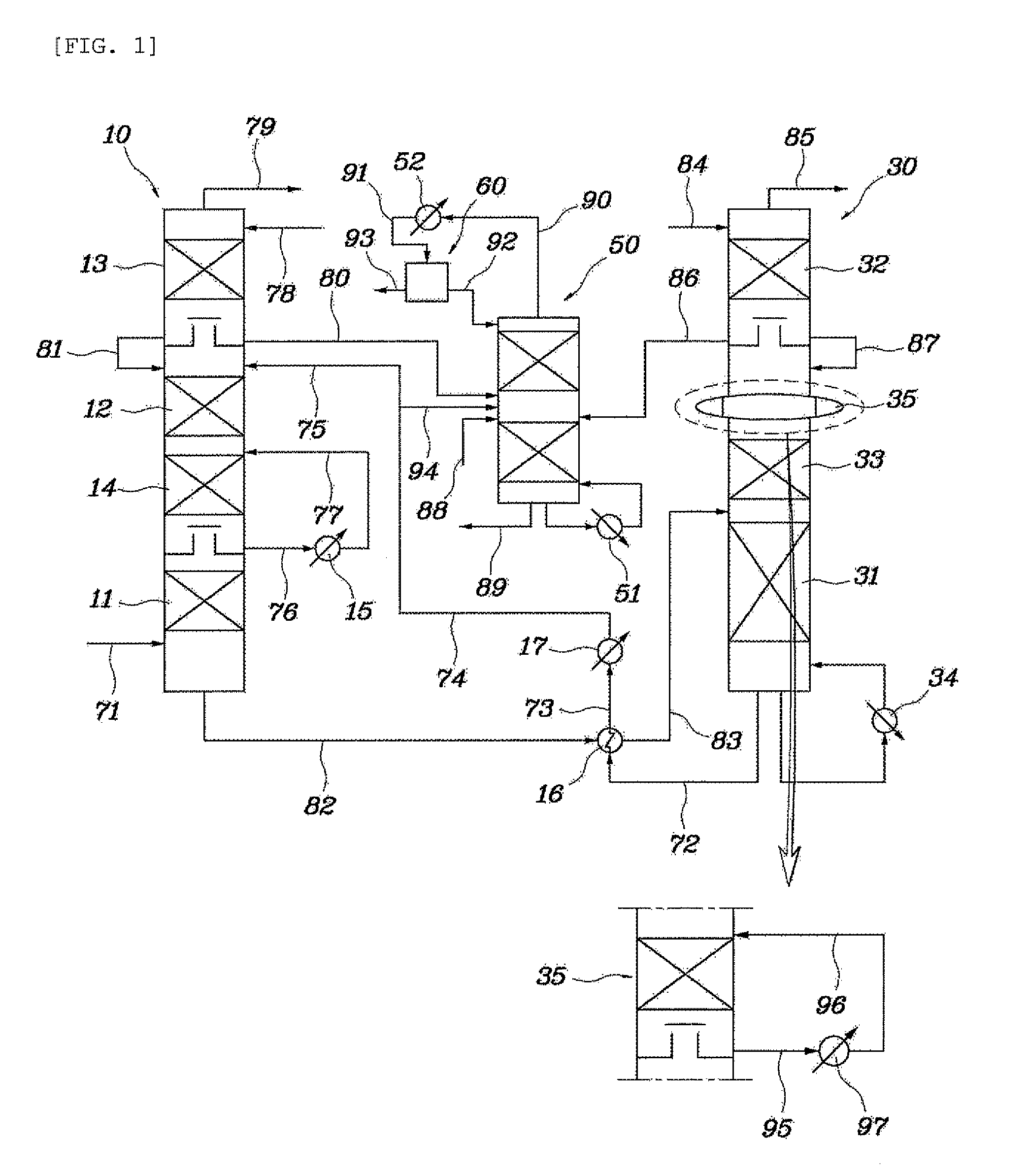
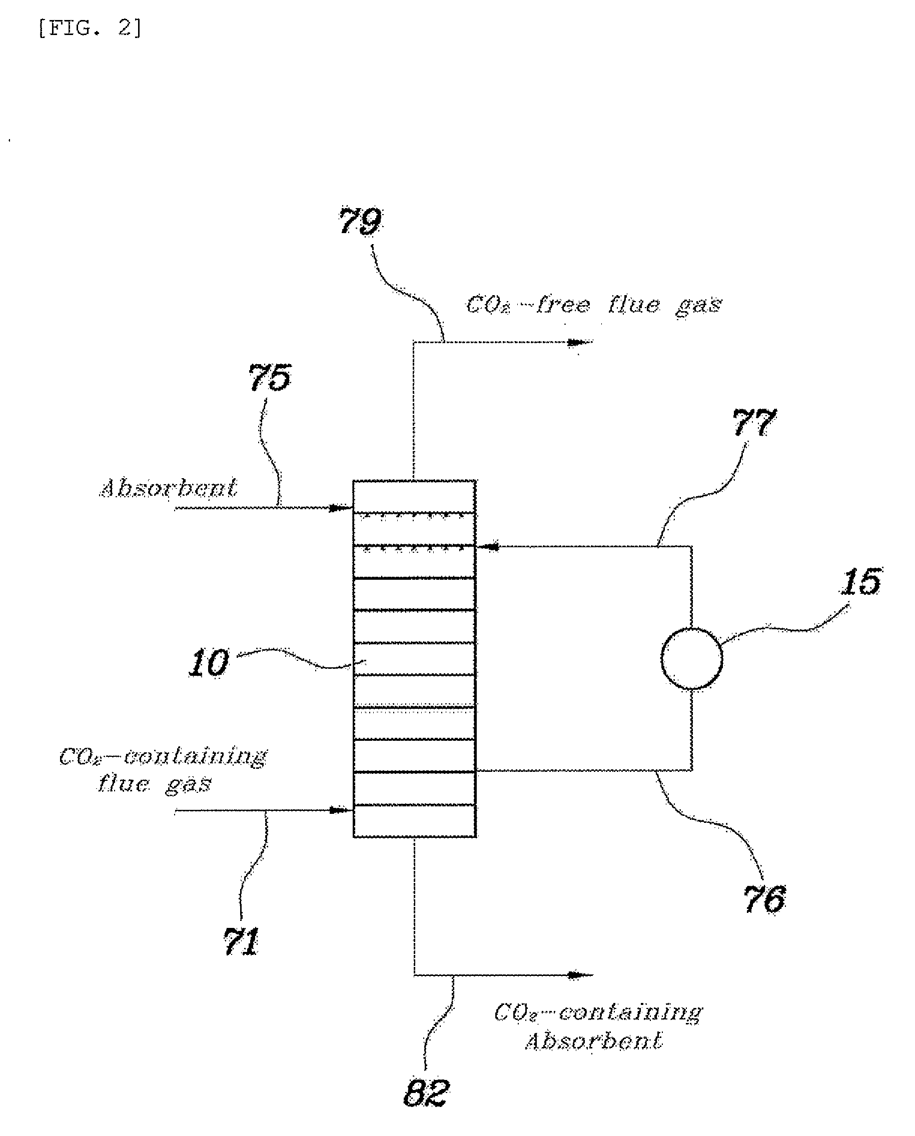
[0049]An absorption column having the same structure and size as in the comparative example and a model gas having the same composition were used, and the absorbent was recovered from the fourth tray from the top of the absorption column, in which the temperature was the highest, cooled to 30° C., and then supplied again to the fourth tray from the top thereof. As such, the amount of the absorbent that was recovered was ⅙ of the amount initially fed to the absorption column.

[0050]As the result of Example 1, the temperature distribution inside the absorption column is depicted in FIG. 4. The carbon dioxide absorption efficiency was determined to be 88%.

example 2

[0051]An absorption column having the same structure and size as in the comparative example and a model gas having the same composition were used, and the absorbent was recovered from the fourth tray from the top of the absorption column, in which the temperature was the highest, cooled to 20° C., and then supplied again to the fourth tray from the top thereof. As such, the amount of the absorbent that was recovered was ⅓ of the amount initially fed to the absorption column.

[0052]As the result of Example 2, the temperature distribution inside the absorption column is depicted in FIG. 5. The carbon dioxide absorption efficiency was determined to be 91%.

example 3

[0053]An absorption column having the same structure and size as in the comparative example and a model gas having the same composition were used, and the absorbent was recovered from the fourth tray from the top of the absorption column, in which the temperature was the highest, cooled to 25° C., and then supplied again to the third tray from the top thereof. As such, the amount of the absorbent that was recovered was ⅓ of the amount initially fed to the absorption column.

[0054]As the result of Example 3, the temperature distribution inside the absorption column is depicted in FIG. 6. The carbon dioxide absorption efficiency was determined to be 91%.

[0055]As is apparent from Examples 1 to 3, part of the high-temperature absorbent was recovered and cooled by the circulation cooler, and was then supplied again into the absorption column, and thereby, the carbon dioxide absorption efficiency was remarkably increased compared to that of the comparative example.

[0056]In the present inve...


PUM

PropertyMeasurementUnit
Temperatureaaaaaaaaaa
Concentrationaaaaaaaaaa

Abstract

An apparatus and method for absorbing and recovering carbon dioxide from flue gas using ammonia water as an absorbent, including an absorption column and a circulation cooler connected to the absorption column so that a high-temperature absorbent is recovered from the absorption column, cooled to a preset temperature, and then supplied again into the absorption column, in order to dissipate absorptive heat generated when carbon dioxide is absorbed from the flue gas.

Description

BACKGROUND OF THE INVENTION[0001]1. Field of the Invention[0002]The present invention relates to an apparatus and method for recovering carbon dioxide from flue gas using ammonia water, and more particularly, to an apparatus and method for recovering carbon dioxide from flue gas using ammonia water, in which absorptive heat, generated in the course of recovering carbon dioxide from flue gas using ammonia water, is effectively dissipated, and the generation of ammonia salt is minimized, thereby increasing recovery efficiency of carbon dioxide.[0003]2. Description of the Related Art[0004]Generally, methods of absorbing and recovering carbon dioxide from flue gas include adsorption, absorption, and membrane separation.[0005]Among these methods, the absorption method is a process of absorbing and recovering carbon dioxide from flue gas using an absorbent. As such, the absorbent is typically exemplified by an amine-based compound. However, the case where the amine-based compound is used ...

Claims


Application Information

Patent Timeline
IPC IPC(8): B01D53/14C01B32/50
CPCB01D53/62B01D53/77B01D53/96B01D2251/2062B01D2251/60B01D2257/504F23J15/02F23J2215/50F23J2219/40Y02C10/04Y02C10/06Y02E20/32Y02C20/40
Inventor KANG, KI JOONLEE, YOUNG BONGKIM, KWANG HYUNKIM, JE YOUNG
Owner RES INST OF IND SCI & TECH
Why Eureka
Try Eureka