Image encoding device, image decoding device, image encoding method and image decoding method

a technology of image encoding and decoding method, applied in the field of image encoding device, image encoding method and image encoding method, can solve problems such as the optimal prediction method

Active Publication Date: 2009-01-01
MITSUBISHI ELECTRIC CORP
View PDF7 Cites 260 Cited by
  • Summary
  • Abstract
  • Description
  • Claims
  • Application Information

AI Technical Summary

Benefits of technology

[0008]According to the image encoding device and the image decoding device of the present invention, in a case of performing encoding that uses multiple color spaces without being limited to the fixed color spaces of Y, Cb, Cr, etc., it is possible to

Problems solved by technology

Therefore, the prediction method is not always optimal for the 4:4:4 format in which the respec

Method used


Image

  • Image encoding device, image decoding device, image encoding method and image decoding method
  • Image encoding device, image decoding device, image encoding method and image decoding method
  • Image encoding device, image decoding device, image encoding method and image decoding method

Examples


first embodiment

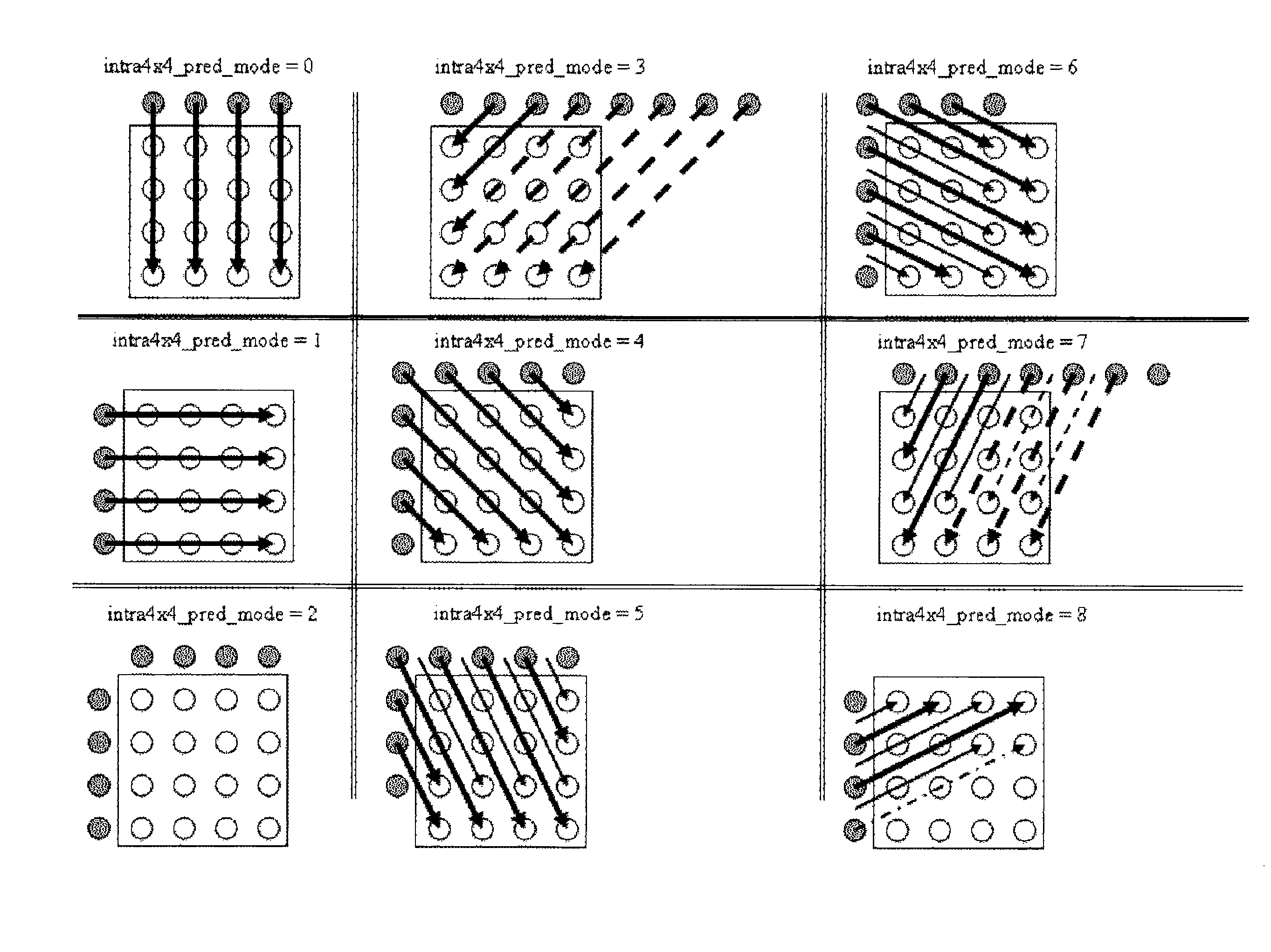
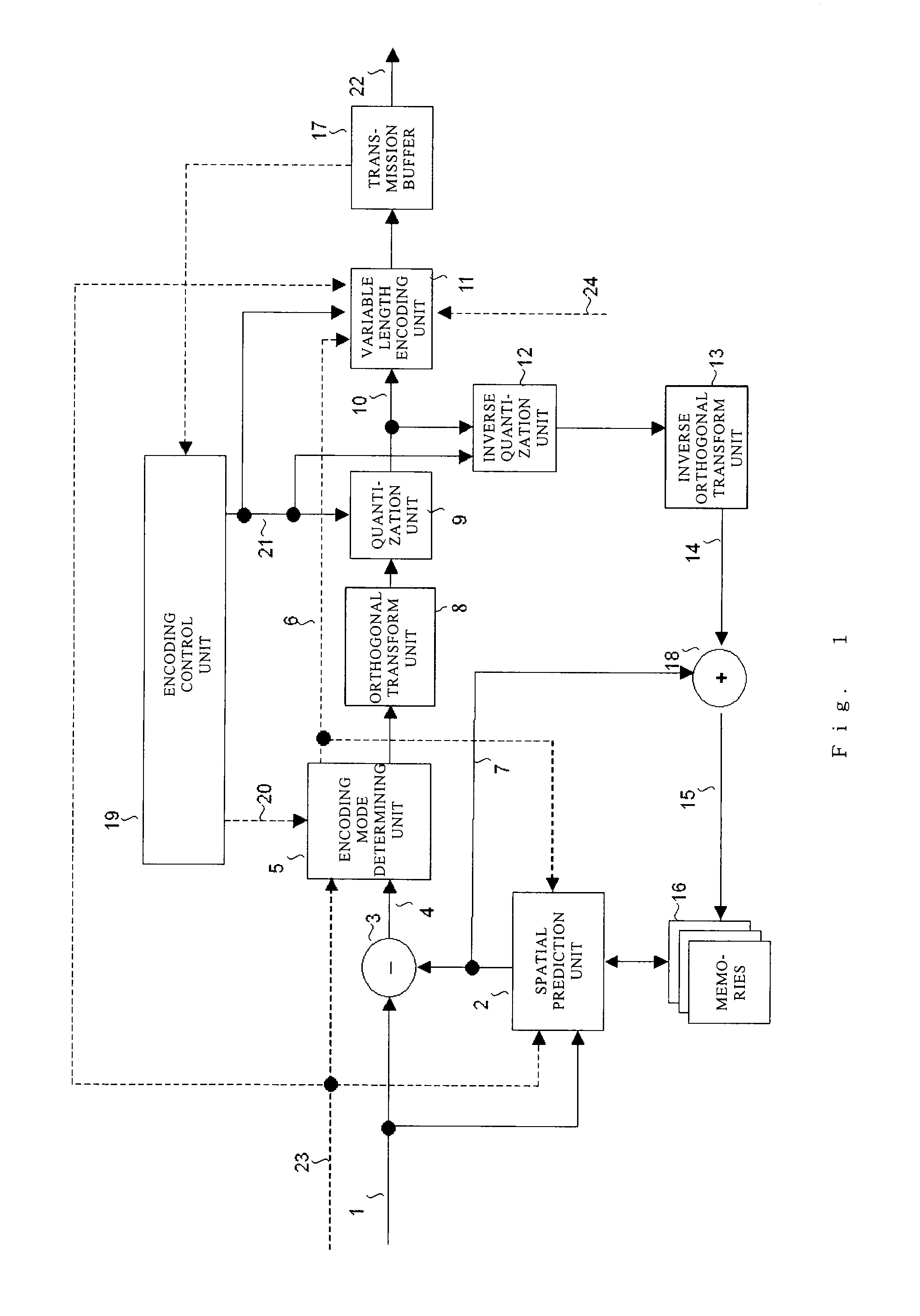
[0108]In a first embodiment of the present invention, an encoding device which performs closed encoding within a frame in units of rectangular regions (macroblocks), each consisting of 16×16 pixels, obtained by equally dividing a video frame input in the 4:4:4 format, and a decoding device corresponding to the encoding device will be described. The encoding device and the decoding device according to the present invention are based on the encoding method employed in Non-patent Document 1 and imparted with characteristics specific to the present invention. Note that in all the embodiments described below, the size of the macroblock is not required to be limited to 16×16 pixels of the frame image. For example, as in the case of an interlaced signal, a 16×16 pixel block of a field image may be a macroblock when a field is used as a screen serving as a unit of encoding. Alternatively, the encoding may be performed while adaptively changing the block size of the macroblock depending on w...

second embodiment

[0146]In the second embodiment of the present invention, another encoding device which performs closed encoding within a frame in units of rectangular areas (macroblocks), each consisting of 16 by 16 pixels, obtained by equally dividing a video frame input in the 4:4:4 format, and a decoding device corresponding to the encoding device will be described. As in the first embodiment of the present invention, the encoding device and the decoding device of this embodiment are provided with characteristics specific to the present invention based on the encoding method employed in Non-patent Document 1 cited above.

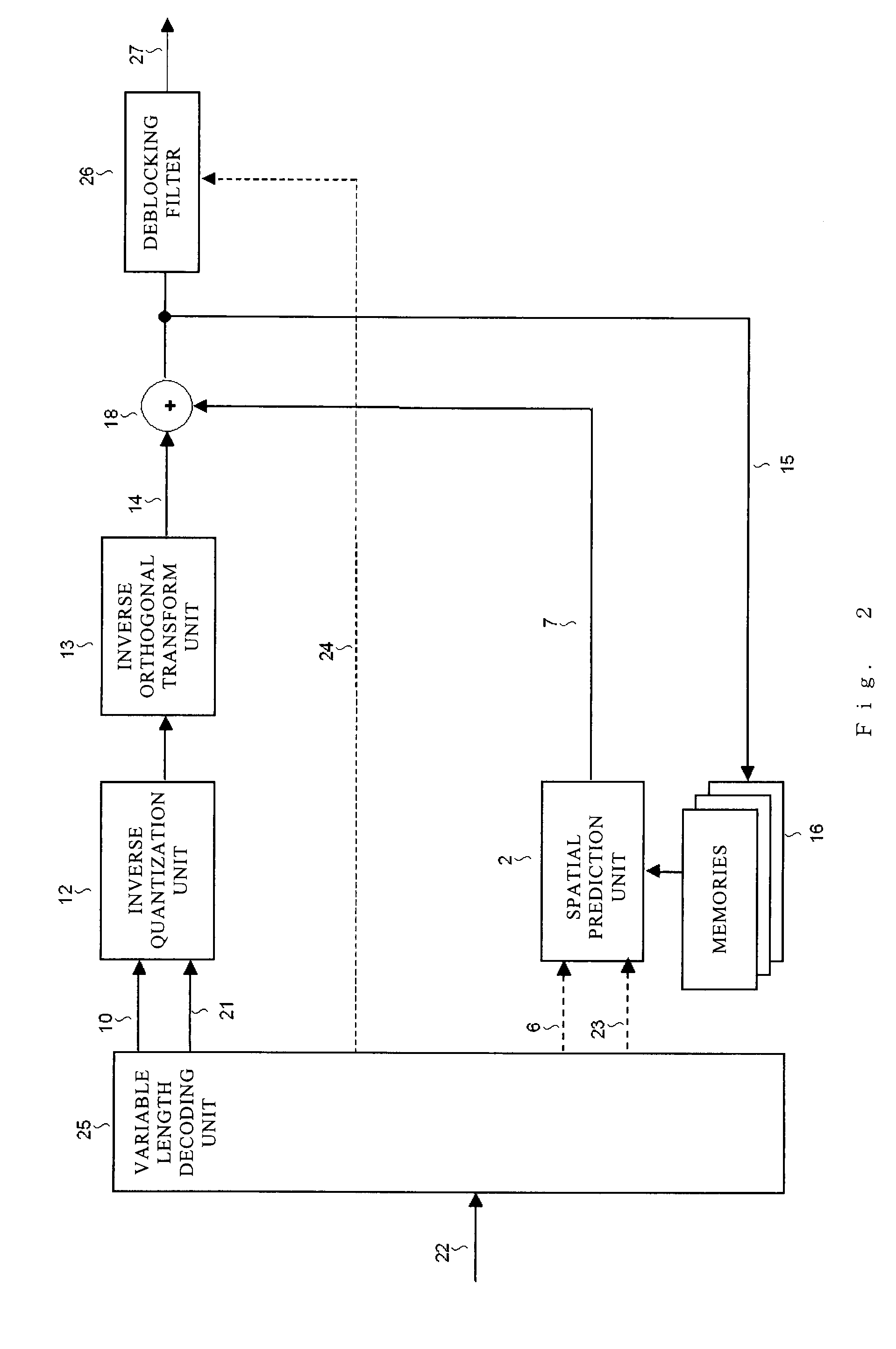
[0147]FIG. 11 illustrates a configuration of a video encoding device, and FIG. 12 illustrates a video decoding device according to the second embodiment of the present invention. In FIG. 11, the components denoted by the same reference numerals as those in the encoding device illustrated in FIG. 1 are the same components. In FIG. 12, the components denoted by the same reference n...

third embodiment

[0190]The third embodiment of the present invention describes another example of the configurations of the encoding device illustrated in FIG. 11 and the decoding device illustrated in FIG. 12. As in the first embodiment of the present invention, the encoding device and the decoding device of the third embodiment are based on the encoding method employed in the MPEG-4 AVC (ISO / IEC 14496-10) / ITU-T H.264 standard corresponding to Non-patent Document 1 and provided with characteristics specific to the present invention. The video encoding device of the third embodiment differs from that illustrated in FIG. 11 of the second embodiment only in the variable length encoding unit 11. The video decoding device of the third embodiment differs from the decoding device illustrated in FIG. 12 of the second embodiment only in the variable length decoding unit 25. The remaining operation is the same as that in the second embodiment, and only differences between the embodiments will be described be...


PUM


Abstract

An encoding device includes a color component separating unit for separating an input bit stream for the respective color components, a block dividing unit for dividing an input color component signal into blocks to generate a signal of an encoding unit area, a predicted image generating unit for generating a predicted image for the signal, a determining unit for determining a prediction mode used for encoding according to a prediction efficiency of the predicted image, a prediction error encoding unit for encoding a difference between the predicted image corresponding to the prediction mode determined by the determining unit and the input color component signal, and an encoding unit for variable length-coding the prediction mode, an output from the prediction error encoding unit, and a color component identification flag indicating the color component to which the input bit stream belongs as a result of the color component separation.

Description

BACKGROUND OF THE INVENTION[0001]1. Field of the Invention[0002]The present invention relates to a digital image signal encoding device, a digital image signal decoding device, a digital image signal encoding method, and a digital image signal decoding method used for an image compression encoding technology or a compressed image data transmission technology.[0003]2. Description of the Related Art[0004]An international standard video encoding system such as MPEG or ITU-T H. 26x has conventionally been premised on use of a standardized input signal format called a 4:2:0 format. The 4:2:0 format is a format where a color moving image signal of RGB or the like is converted into a luminance component (Y) and two chrominance components (Cb, Cr), and the number of chrominance component samples is reduced to half of luminance components both in horizontal and vertical directions. The chrominance component is inferior to the luminance component in visibility. Accordingly, the conventional i...

Claims


Application Information

Patent Timeline
IPC IPC(8): H04N11/00H04N19/593
CPCH04N19/176H04N19/147H04N19/61H04N19/593H04N19/11H04N19/107H04N19/517H04N19/117H04N19/91H04N19/186H04N19/19H04N19/436H04N19/523H04N19/109H04N19/103H04N19/13
Inventor SEKIGUCHI, SHUNICHIYAMAGISHI, SHUICHIMORIYA, YOSHIMIYAMADA, YOSHIHISAASAI, KOHTAROMURAKAMI, TOKUMICHIIDEHARA, YUICHI
Owner MITSUBISHI ELECTRIC CORP
Why Eureka
Try Eureka