Display Device

a display device and liquid crystal technology, applied in static indicating devices, instruments, optics, etc., can solve the problems of reducing the dynamic range of the display device, restricting the freedom of patterning the backlight into emitting regions, and not being able to further divide the light emitting regions. , to achieve the effect of minimizing the increase in the cost of driving system and manufacturing

Inactive Publication Date: 2009-02-12
SHARP KK
View PDF18 Cites 17 Cited by
  • Summary
  • Abstract
  • Description
  • Claims
  • Application Information

AI Technical Summary

Benefits of technology

[0020]The present invention was made to solve the foregoing problems, and it is an object of the present invention to provide a display device which displays an image by using a display panel and a backlight (backlight source), and which device, in cases where the emitting regions of the backlight is...

Problems solved by technology

Meanwhile, it is believed that a liquid crystal display device does not achieve the displaying performance of a CRT in terms of dynamic range of displaying.
First, when the divided-screen active backlight driving of Patent Documents 2 to 4 is performed in a liquid crystal display device, the arrangement and shape of lig...

Method used


Image

  • Display Device
  • Display Device
  • Display Device

Examples


embodiment 1

[0056]The following describes a display device of the present embodiment, with reference to FIG. 1 to FIG. 6(a), FIG. 6(b), and FIG. 6(c).

[0057]Note that a display device in the present embodiment is a liquid crystal display device; however, the display device is not limited to the liquid crystal display device. Other types of display devices such as an electrophoresis display can be adopted as the display device, provided that a back area light source (backlight) is used.

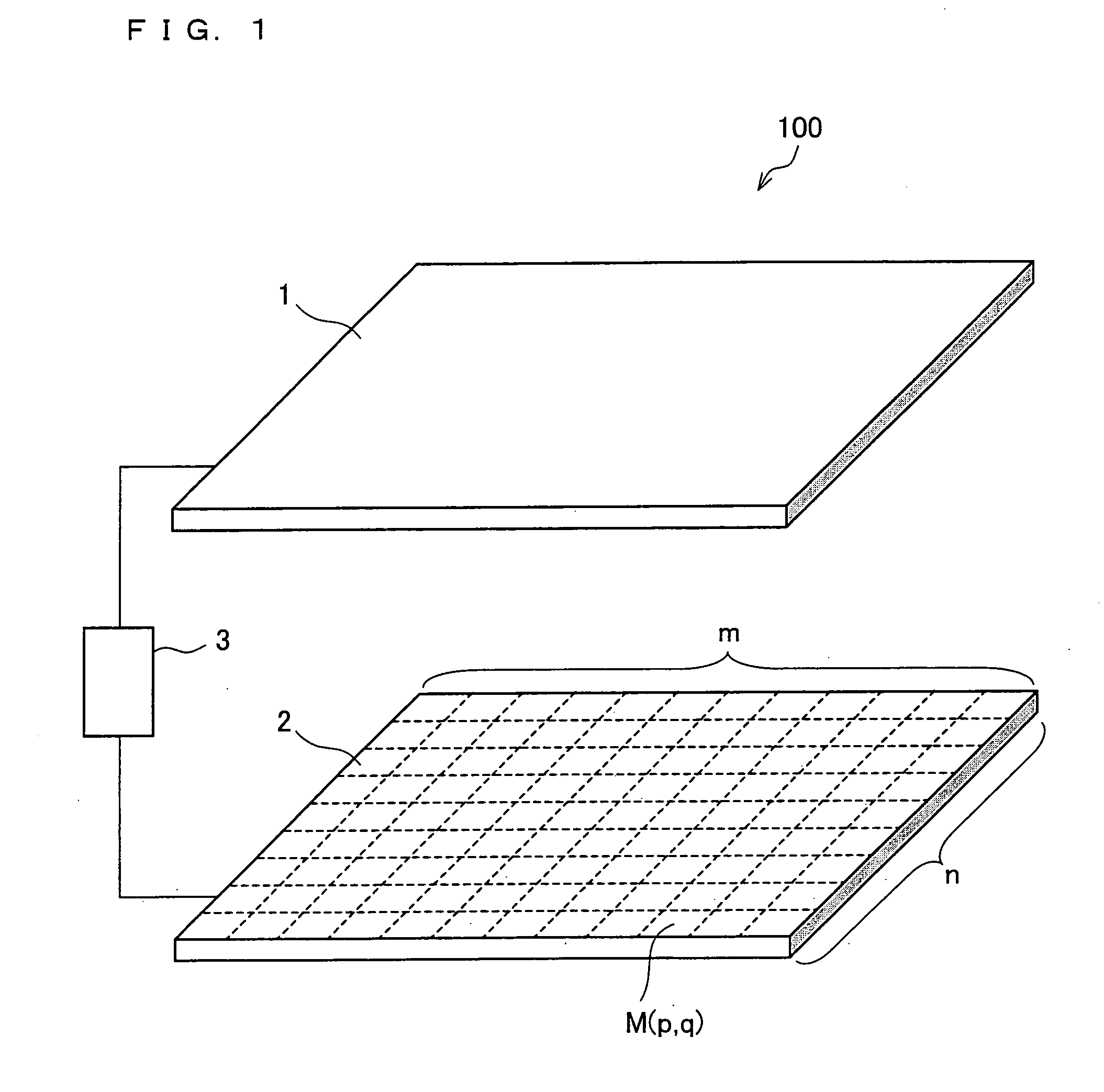
[0058]FIG. 1 is a perspective diagram showing a schematic configuration of the display device of the present invention. As shown in the figure, the display device 100 includes: a display panel 1 (liquid crystal panel in this case), a backlight 2, and a controlling section 3. The backlight 2 is provided on a back face side (on a surface opposite to the displaying surface) of the display panel 1. This display panel 1 is a transmissive display panel which displays an image by having light from the backlight 2 pass the...

embodiment 2

[0134]The following describes a display device of another embodiment according to present invention.

[0135]The display device of the present embodiment is the same as the display device of the foregoing embodiment 1, except for the relationship between sizes of the unit emitting pixels; divided emitting region; and unit display pixels. In the liquid crystal display device of present embodiment, the respective configurations of a display panel, a backlight, and a controlling section are the same as those described in the embodiment 1, and explanations therefor are omitted here.

[0136]Next described with reference to FIG. 7(a) to FIG. 7(c) is the relationship amongst sizes of (i) the unit emitting pixels N(j′, k′) of the area light source, (ii) divided emitting region M(p′, q′), and (iii) the unit display pixels L(m, n), in the display device of the present embodiment. FIG. 7(a) is a plane view showing a layout of pixels of the display panel 1 in the display device of the present embodi...

embodiment 3

[0153]The following describes a display device of yet another embodiment according to present invention.

[0154]The display device of the present embodiment is the same as the display devices of the foregoing embodiments 1 and 2, except for the layout of unit emitting pixels of a backlight. In the liquid crystal display device of present embodiment, the respective configurations of a display panel and a controlling section are the same as those described in the embodiment 1, and explanations therefor are omitted here.

[0155]Next described with reference to FIG. 9(a) to FIG. 9(c) is the layout of unit emitting pixels of a backlight in the display device of the present embodiment. FIG. 9(a) is a plane view showing a layout of pixels of the display panel 1 in the display device of the present embodiment. FIG. 9(b) is a diagram showing a division pattern formed by dividing the emitting region of the backlight into a matrix of m (rows)×n (columns), so as to perform a divided-screen active b...


PUM


Abstract

In one embodiment of the present invention, a display device is disclosed which performs a divided-screen active driving, and which allows (i) its emitting region to be divided into smaller units, irrespective of the smallest module unit of a light source; and (ii) minimizing increase in costs for a driving system and manufacturing of an area light source, a display device of the present invention includes: a display panel having unit display pixels; an area light source arranged on a back surface of the display panel, the area light source having an emitting region which is divided into divided emitting regions; and a controlling section for controlling luminance of each of the divided emitting regions of the area light source, based on luminance information of video signals input, wherein the area light source includes: unit emitting pixels which controls light emission of the divided emitting regions through a matrix driving; the unit emitting pixels each having an electron emitting element for emitting an electron, and a fluorescent substance which emits light by being excited by the electron emitted from the electron emitting element, the unit emitting pixels each occupying an area which is equivalent to an area of plural pixels out of the unit display pixels.

Description

TECHNICAL FIELD[0001]The present invention relates to a display device, particularly to a display device which displays an image by using a display panel and a backlight (backlight source).BACKGROUND ART[0002]Liquid crystal display devices (LCDs) have been used as display devices in many occasions in recent years. Amongst those, active-matrix-driven LCDs having a thin film transistor for each pixel are widely used in flat-screen television sets, laptop computers, monitors of desktop computers, and the like, because of their low thickness and light weight, and their characteristics such as low-power consumption, high resolution, and high contrast.[0003]The configuration of each active-matrix-driven LCD used today includes a liquid crystal panel (display panel) and a backlight. The liquid crystal panel which includes two glass substrates interposing therebetween liquid crystal has a color filter. On the back surface of this liquid crystal panel, the backlight is provided.[0004]In many...

Claims


Application Information

Patent Timeline
IPC IPC(8): G09G5/10
CPCG02F1/133602G02F2001/133625G09G3/22G09G3/3413G09G2360/16G09G2300/0426G09G2300/0439G09G2310/0235G09G3/3426G02F1/133625
Inventor ISHIZUMI, TAKASHIIZUMI, YOSHIHIROYAMANE, YASUKUNI
Owner SHARP KK
Why Eureka
Try Eureka