Synchronous signal generator for trim balancing of jet engine

a technology of synchronous signal generator and jet engine, which is applied in the direction of machines/engines, liquid fuel engines, instruments, etc., can solve the problems of difficult to directly measure the rotational frequency and position of the hp shaft during the trim balancing trial run, and controllers cannot determine which of these pulses to produ

Inactive Publication Date: 2009-03-05
HONEYWELL INT INC
View PDF11 Cites 7 Cited by
  • Summary
  • Abstract
  • Description
  • Claims
  • Application Information

AI Technical Summary

Problems solved by technology

If the discs are not properly balanced (i.e., if the mass of the discs is not evenly distributed about the longitudinal axis of the HP shaft), vibrations may be produced as the HP shaft rotates.
When the jet engine is assembled, the HP shaft is contained within the engine's nacelle; it is thus difficult to directly measure the rotational frequency and position of the HP shaft during the trim balancing trial runs.
The controller cannot determine which of these pulses represents a full revolution of the HP shaft through multiple trial runs.
As a result, the timing pulse may become unsynchronized with the HP spool between engine starts during the trim balancing process.
Due to this asynchronization, it may be difficult to determine the proper location at which weight should be added or removed without the performance of a significant number of trial runs; e.g., utilizing conventional trim balancing techniques and equipment, eight trial runs are typically necessary for two plan trim balancing.
The performance of multiple trial runs is thus time consuming and costly.
In addition, each trial run results in additional wear to the jet engine consequently decreasing the engine's life and overall value.

Method used


Image

  • Synchronous signal generator for trim balancing of jet engine
  • Synchronous signal generator for trim balancing of jet engine
  • Synchronous signal generator for trim balancing of jet engine

Examples


Embodiment Construction

[0012]The following detailed description of the invention is merely exemplary in nature and is not intended to limit the invention or the application and uses of the invention. Furthermore, there is no intention to be bound by any theory presented in the preceding background of the invention or the following detailed description of the invention. In this regard, although a three spool turbofan gas turbine engine is described for illustrative purposes below, it will be appreciated that the invention may be utilized with other types of multi-spool aircraft engine.

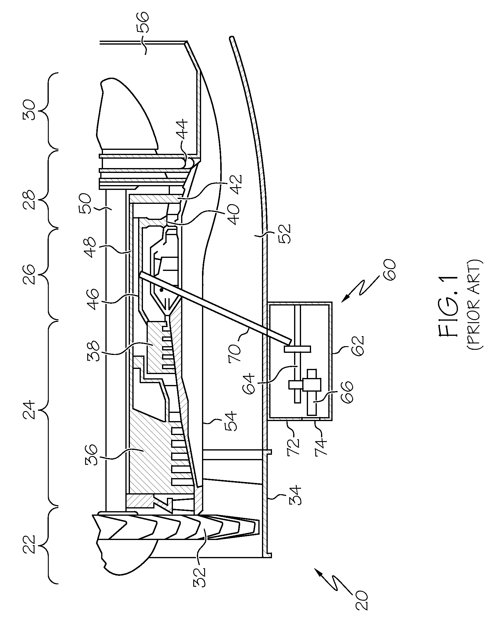
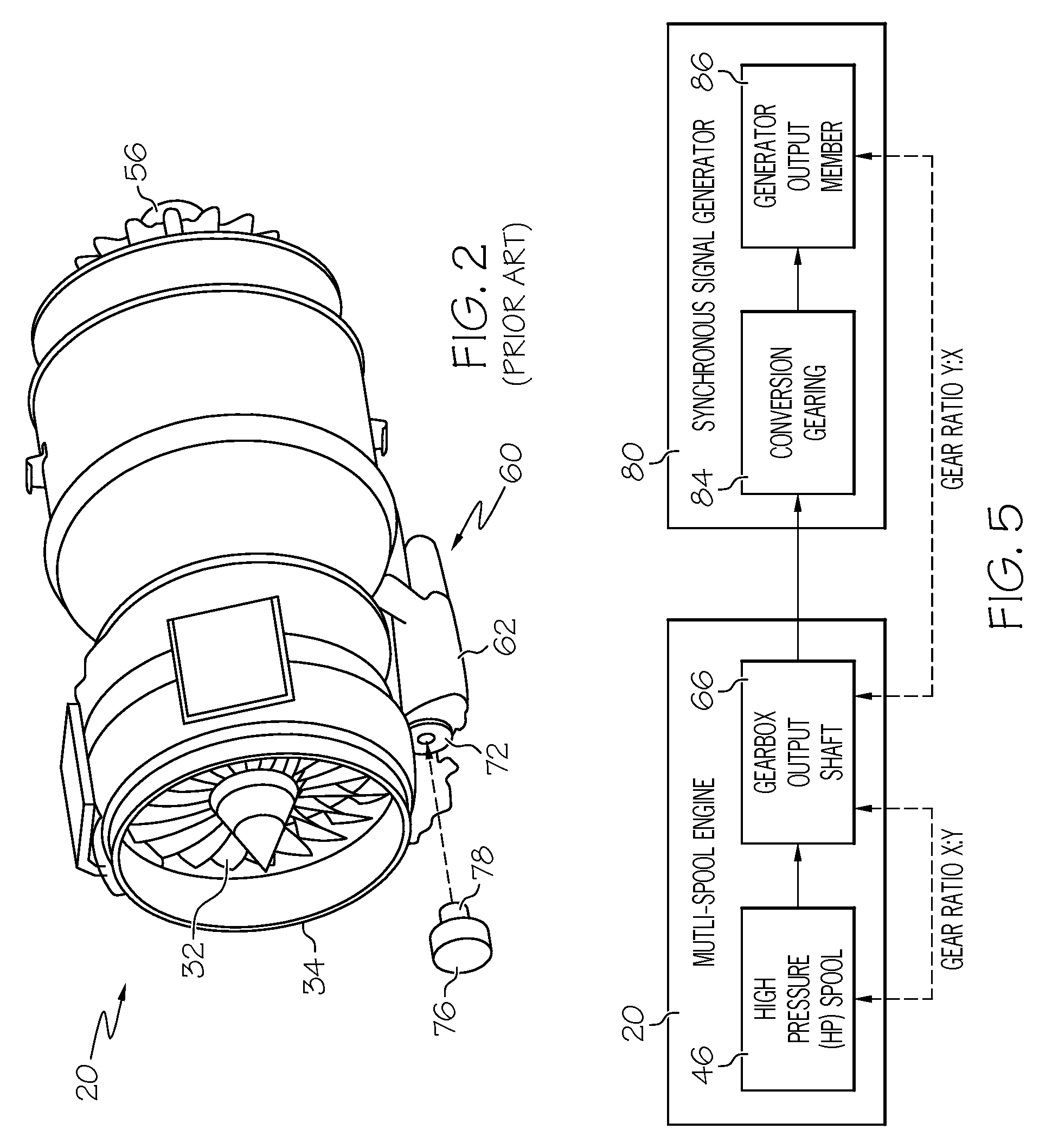
[0013]FIGS. 1 and 2 are cross-section and isometric views of a multi-spool jet engine 20 of the type conventionally deployed on an aircraft. In this particular example, multi-spool jet engine 20 is a three spool turbofan gas turbine engine. As shown in FIG. 1, jet engine 20 may have an intake section 22, a compressor section 24, a combustion section 26, a turbine section 28, and an exhaust section 30. Intake section 22 includ...


PUM


Abstract

A synchronous signal generator is provided for use in conjunction with an aircraft engine having a spool and an engine output shaft driven by the spool. The synchronous signal generator includes a generator housing, a generator output member rotatably mounted in the generator housing, a once-per-revolution timing mark on the generator output member, and conversion gearing disposed within the housing and configured to couple the engine output shaft to the generator output member. The conversion gearing rotates the generator output member at substantially the same rotational frequency as the spool when the conversion gearing is coupled to the engine output shaft.

Description

FIELD OF THE INVENTION[0001]The present invention relates generally to jet engines, and, more particularly, to a synchronous signal generator for use in the trim balancing of a multi-spool aircraft engine.BACKGROUND OF THE INVENTION[0002]A multi-spool jet engine (e.g., a turbofan engine) typically includes a high pressure (HP) spool, which supports a high pressure compressor and a high pressure turbine. The high pressure compressor and the high pressure turbine may each include one or more bladed discs that extend radially outward from the HP shaft. As the HP shaft rotates, so too do the bladed discs. If the discs are not properly balanced (i.e., if the mass of the discs is not evenly distributed about the longitudinal axis of the HP shaft), vibrations may be produced as the HP shaft rotates.[0003]To decrease or eliminate vibrations, the bladed discs forming the high pressure turbine and those forming the high pressure compressor may be balanced individually or simultaneously. In ge...

Claims


Application Information

Patent Timeline
Patent Type & Authority Applications(United States)
IPC IPC(8): F01D25/04G01M1/22G01B7/00
CPCF02C7/36
Inventor SHILO, MARK A.TALBERT, PAUL B.ALAM, MOHSIUL
Owner HONEYWELL INT INC
Why Eureka
Try Eureka