Image forming apparatus and image developer used therein

a technology of image developer and forming apparatus, which is applied in the direction of electrographic process apparatus, instruments, optics, etc., can solve the problems of image difficulty in obtaining a space for containing the developer in the image developer, and the developer's deviation of toner concentration in the developer, so as to achieve the effect of sufficient stirring effect of the developer

Active Publication Date: 2009-03-19
RICOH KK
View PDF17 Cites 5 Cited by
  • Summary
  • Abstract
  • Description
  • Claims
  • Application Information

AI Technical Summary

Benefits of technology

[0008]Accordingly, an object of the present invention is to provide an image forming apparatus capable of obtaining a sufficient stirring effect of the developer even when having insufficient vacant spaces in the paths in the developer container.

Problems solved by technology

Therefore, the image developer has deviation of toner concentration in the developer due to insufficient stir less than an image developer having none of such circulation paths.
However, even the image developer including the circulation paths has a deviation of toner concentration in the developer unless the developer is fully stirred on the second path.
Recent image forming apparatuses are becoming smaller, and an image forming engine has smaller capacity, resulting in difficulty of obtaining a space for containing a developer in the image developer.
Consequently, in the image developer, each path in a developer container containing the developer is mostly occupied with the developer and does not have sufficient vacant space.
When the path in the developer container does not have sufficient vacant space, the developer cannot widely move even when stirred and the developers in separated places are difficult to exchange each other.
Therefore, even the image developer disclosed in Japanese published unexamined application No. 2004-205535 cannot obtain a sufficient stirring effect when having insufficient vacant spaces, resulting in difficulty of reducing the deviation of the toner concentration.

Method used


Image

  • Image forming apparatus and image developer used therein
  • Image forming apparatus and image developer used therein
  • Image forming apparatus and image developer used therein

Examples


Embodiment Construction

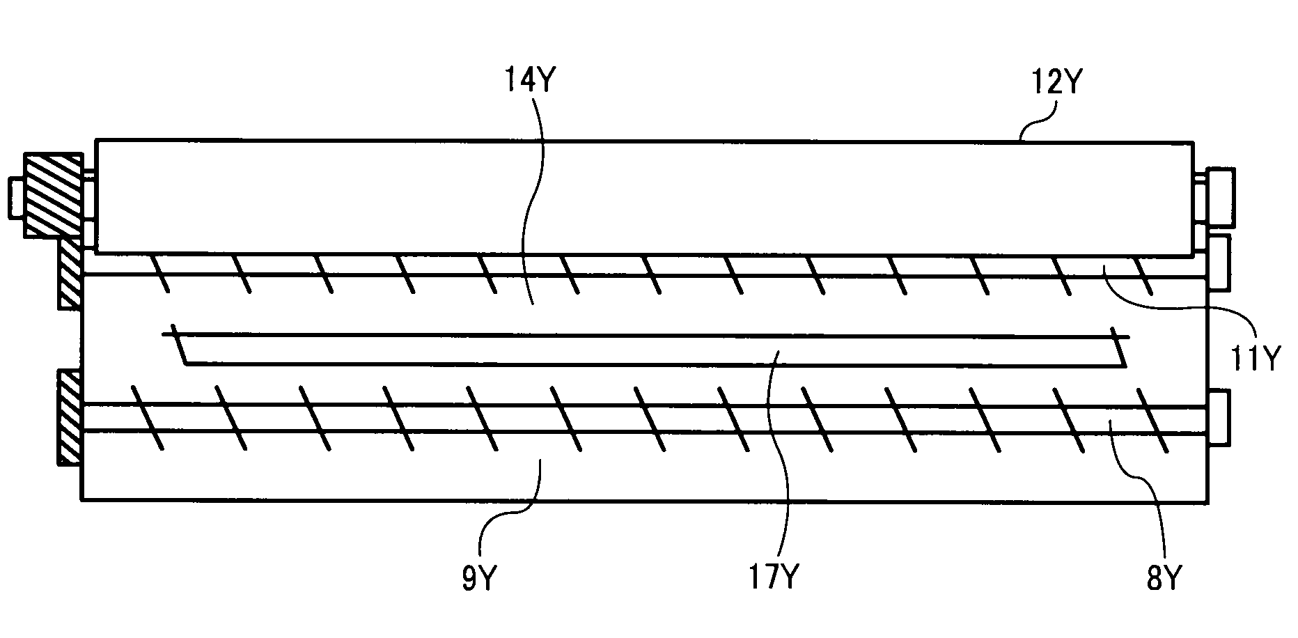
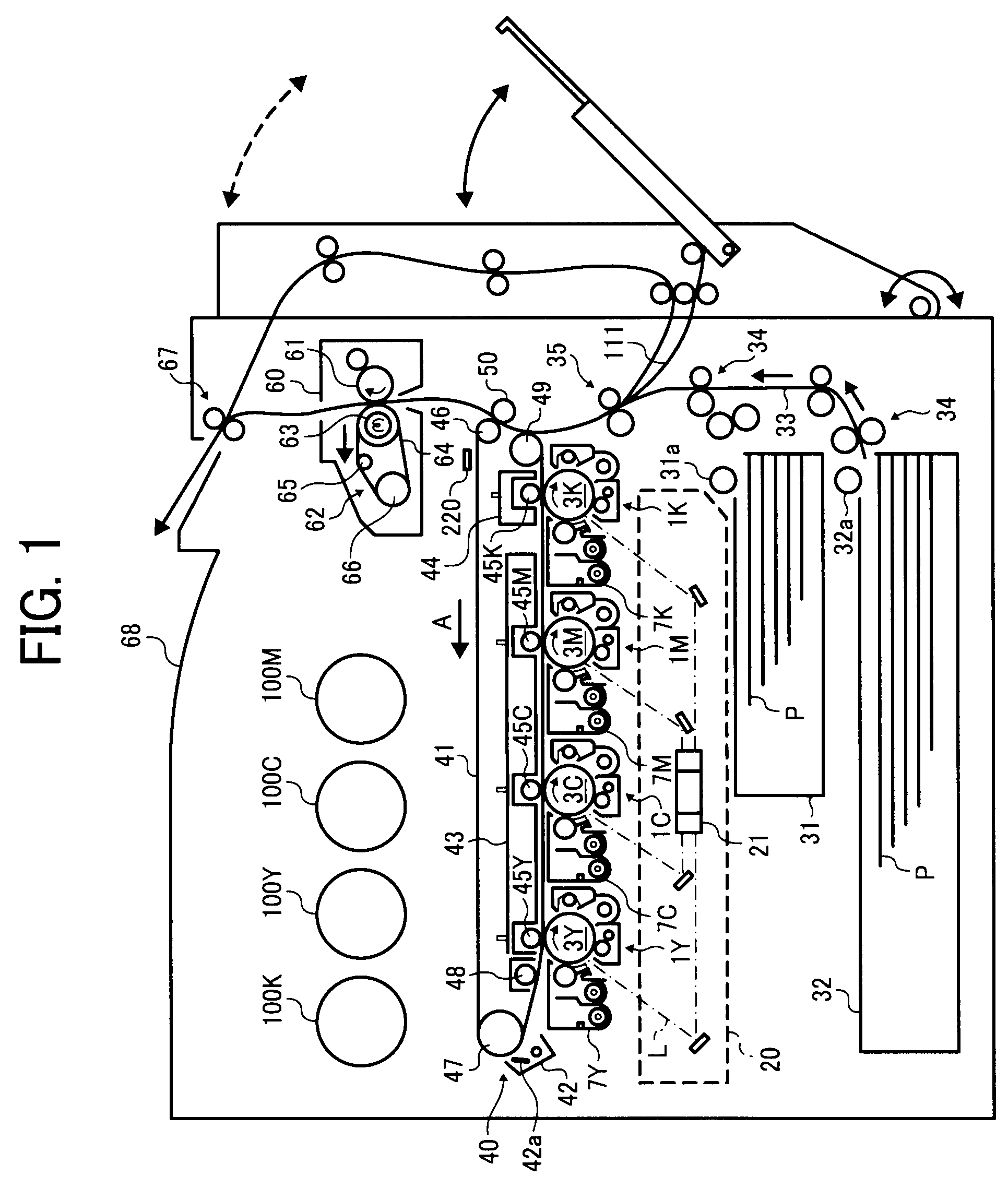
[0036]The present invention provides an image forming apparatus capable of obtaining a sufficient stirring effect of the developer even when having insufficient vacant spaces in the paths in the developer container. More particularly, the present invention provides an image forming apparatus, comprising:

[0037]a latent image bearer configured to bear a latent image on the surface and move the surface;

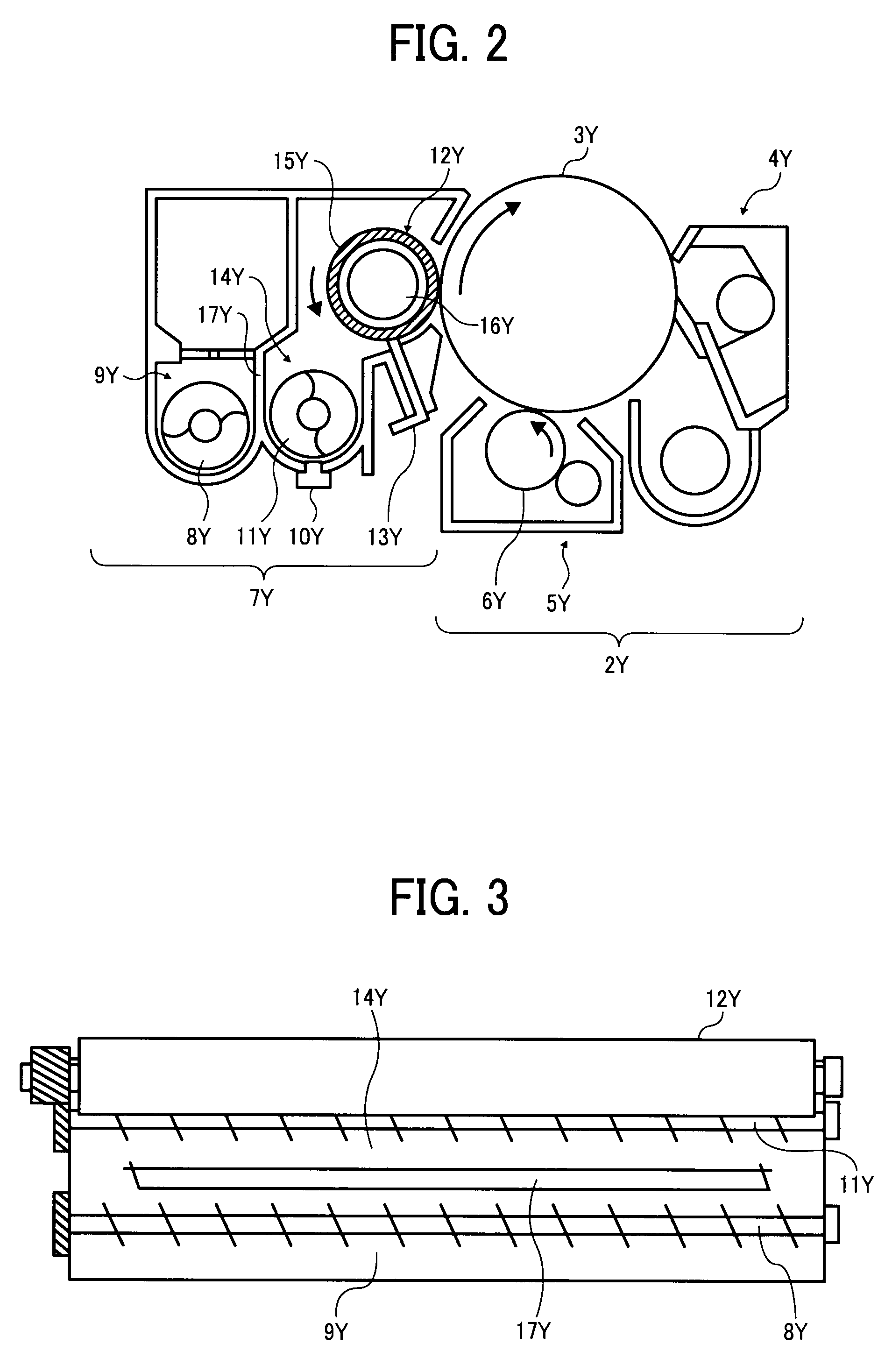
[0038]an image developer configured to feed a toner in a two-component developer comprising the toner and a carrier to the latent image in a developing area facing the latent image bearer to develop the latent image and to form a toner image,

[0039]wherein the image developer comprises:[0040]a developer container configured to contain the two-component developer, comprising circulation paths comprising a first path through which the developer fed onto the surface of the developer bearer passes and a second path connected with the first path directly or through another path; and[0041]a dev...


PUM


Abstract

An image forming apparatus, including a surface-traveling latent image bearer bearing a latent image on the surface thereof; an image developer feeding a toner in a two-component developer including the toner and a carrier to the latent image in a developing area facing the latent image bearer to develop the latent image to form a toner image, including a developer stirrer and feeder circulating the two-component developer in circulation paths while stirring the two-component developer, including a driver independently driving the first and the second stirring and feeding members; a transferer transferring the toner image onto a recording material; and a controller controlling the driver such that an amount of the two-component developer fed by the second stirring and feeding member per unit time is relatively larger than that of the two-component developer fed by the first stirring and feeding member when a predetermined increase condition of stirring is satisfied.

Description

BACKGROUND OF THE INVENTION[0001]1. Field of the Invention[0002]The present invention relates to an image forming apparatus such as a copier, a printer and a facsimile using a two-component developer including a toners and a carrier, and to an image developer used therein.[0003]2. Discussion of the Background[0004]Typically, in an image forming apparatus using a two-component developer (hereinafter referred to as a “developer”), a toner consumed for development is fed into the developer and the developer is stirred to recover the concentration of the toner of the developer in the image developer and perform constant developability even when time passes. Recently, the image developer includes circulation paths including at least a first path the developer fed onto the surface of a developer bearer passes through and a second path connected with the first path directly or through another path. The image developer stirs the developer in the second path and feed the developer to the fir...

Claims


Application Information

Patent Timeline
Patent Type & Authority Applications(United States)
IPC IPC(8): G03G15/10
CPCG03G2215/0132G03G15/0877G03G15/0865G03G2215/0822
Inventor KASAI, TADASHI
Owner RICOH KK
Why Eureka
Try Eureka