Split shaft for high power diesel engine

Inactive Publication Date: 2009-04-02
GENERAL ELECTRIC CO
View PDF5 Cites 7 Cited by
  • Summary
  • Abstract
  • Description
  • Claims
  • Application Information

AI Technical Summary

Benefits of technology

[0004]The present invention provides a novel idler shaft assembly designed to respond to such needs. The assembly may be used in a wide range of engine applications, but is particularly well-suited for transferring power between a crank shaft and a cam shaft in a heavy duty engine. The assembly allows for the crank shaft to drive the cam shaft in normal operation, but also may transfer power from the cam shaft back to the crank shaft during certain periods of operation. The assembly may include two gears, a large idler gear and a small idler gear. The idler shaft assembly itself supports these gears, with the small idler gear being interference fit on a hollow shaft of the assembly. The large idler gear may be interference fit on the small idler gear. Idler hubs are mounted on either side of the hollow shaft, and these are drawn into tight engagement with the idler shaft by means of fasteners. The idler hubs effectively center the hollow shaft, and thereby the gears, with respect to support structures, such as left and right crankcase supports. Rotation of the assembly is facilitated by bearings interposed between the crankcase supports and the idler hubs. The entire structure may be lubricated by means of a lubricant that can flow through the hollow shaft and passages in the idler hubs to the bearings.

Problems solved by technology

The large idler gear may be interference fit on the small idler gear.

Method used


Image

  • Split shaft for high power diesel engine
  • Split shaft for high power diesel engine
  • Split shaft for high power diesel engine

Examples


Embodiment Construction

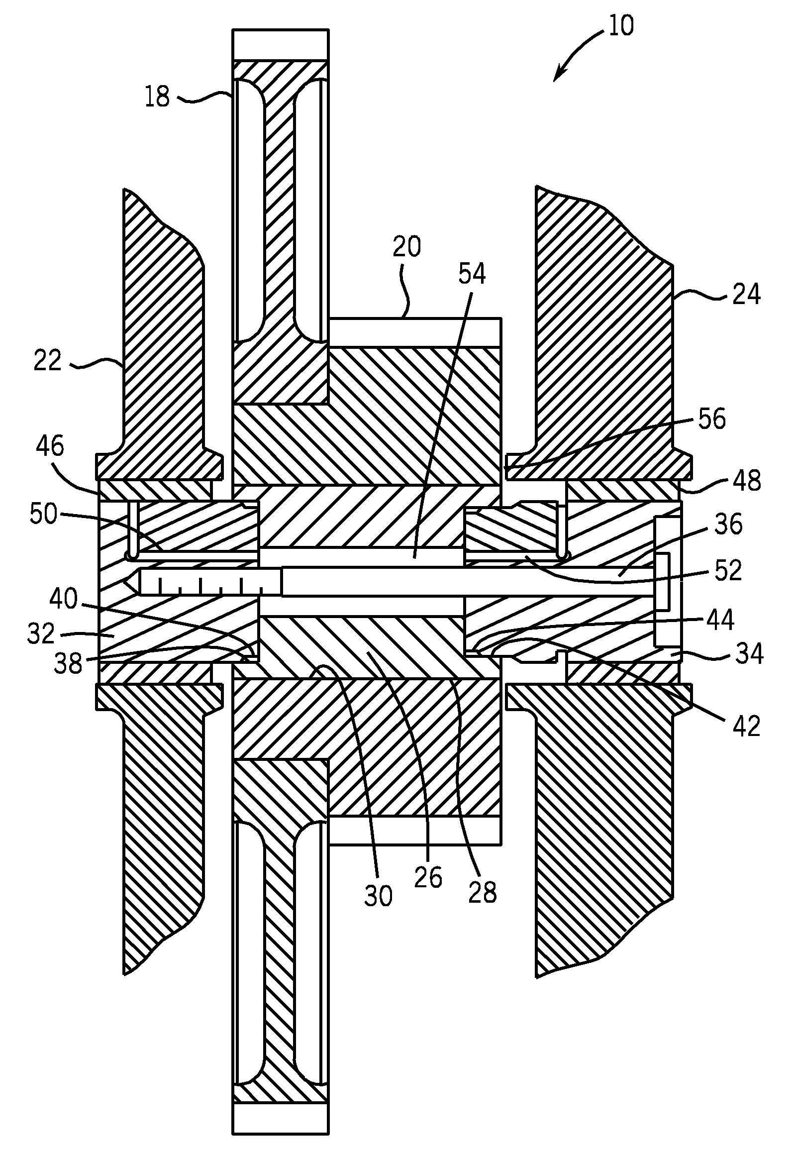
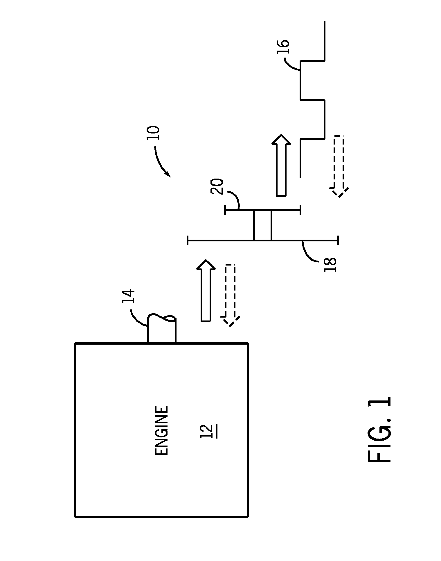
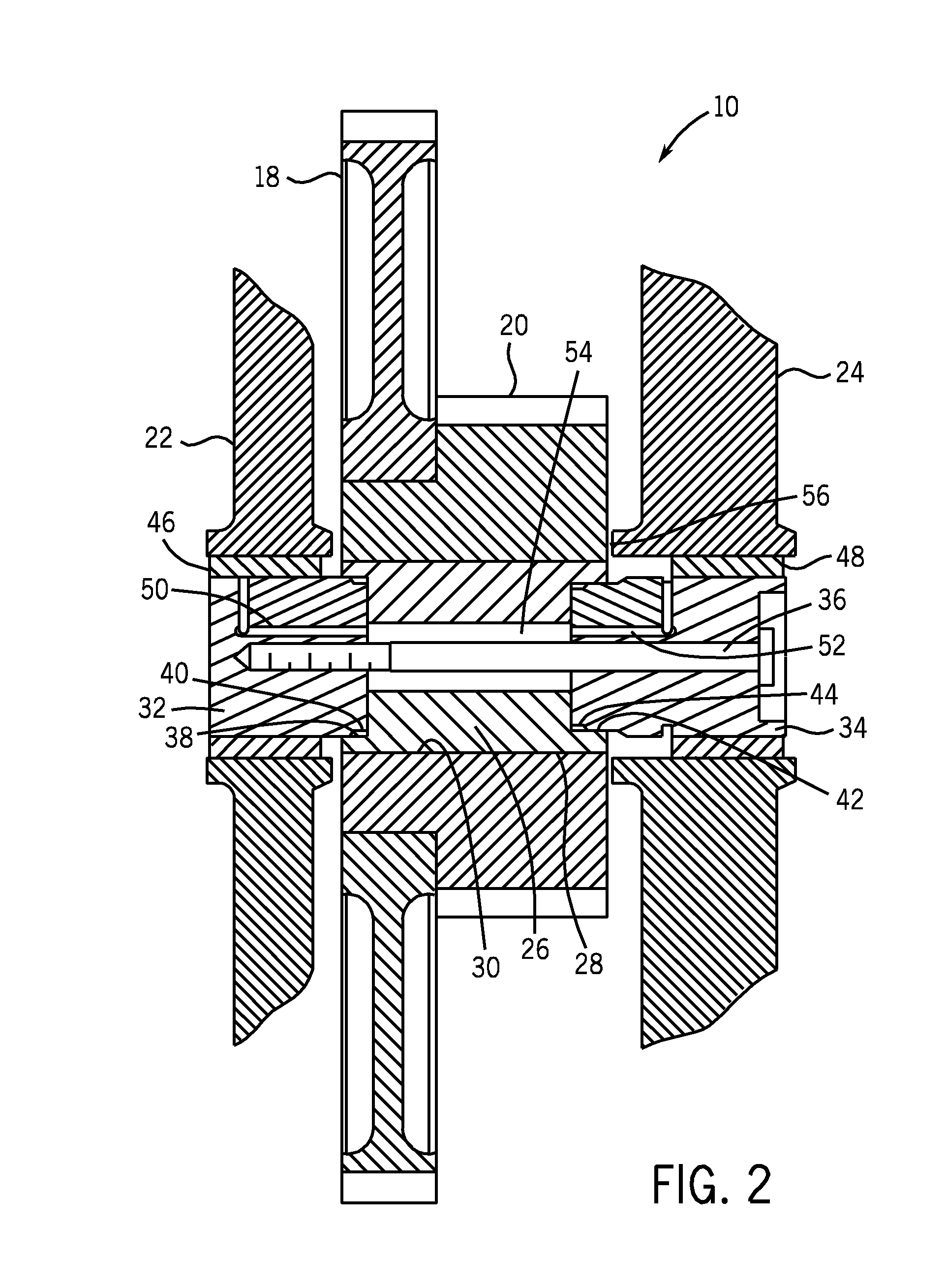
[0014]Turning now to the drawings, and referring first to FIG. 1, a diagrammatical representation is provided of an idler shaft assembly 10 used in conjunction with an engine 12. The engine may be any type of internal combustion engine, but in a present context may be a heavy duty diesel engine, such as those used for locomotives, ships and boats, off-road tractors, tractor-trailers, engine-driven generators, and so forth. As will be appreciated by those skilled in the art, the engine 12 is forced and maintained in motion by combination of fuel with an oxidant, that is combusted in internal cylinders of the engine (not shown) to force a crank shaft 14 to rotate. Useful work may be drawn from this shaft, such as to drive a generator, a propulsion gear train with wheels, propellers, and so forth. The idler shaft assembly 10 serves to transmit torque between the crank shaft 14 and a cam shaft 16. The cam shaft 16 is designed to open and close valving (not shown) for the cylinders of th...


PUM


Abstract

An idler shaft assembly is disclosed suitable for internal combustion engines, such as the heavy duty engines. The assembly may transmit power between a crank shaft and a cam shaft. The assembly includes a hollow shaft which can be interference fit within a small idler gear, with a large idler being mounted on a shoulder of the small idler gear. Idler hubs on either side of the hollow shaft are centered with respect to the idler shaft and are held firmly in place by fasteners that extend through one of the hubs and the hollow shaft, and are threaded into the other hub. Lubrication may be provided by an internal reservoir formed in the hollow shaft, and oil passages in fluid communication with this reservoir that extend to journal bearings mounted between the idler hubs and the support structure for the overall assembly.

Description

BACKGROUND[0001]The present invention relates generally to internal combustion engines, and more particularly to a novel idler shaft assembly for such engines.[0002]Various designs of internal combustion engines have been proposed and many designs have been placed into service. In general, such engines include a series of pistons that are reciprocally mounted in an engine block and that drive a crank shaft in rotation in response to combustion of fuel and oxidant in the engine cylinders. Current engine designs that utilize this general scheme include gasoline engines, diesel engines, and similar engines designed to work on other fuels. In addition to turning the crank shaft, large engines include internal power transmission drive trains for servicing the engine itself. By way of example, certain internal combustion engines utilize gearing to transfer power from the crank shaft to drive a cam shaft used to open and close valving for the cylinders. Other internal power transmission dr...

Claims


Application Information

Patent Timeline
IPC IPC(8): F16H3/08
CPCF01L1/026F01L2101/00F01L2103/00Y10T74/19219F01M1/06F16H55/17F16H57/023F01L2810/02F01L2301/00F01L2303/00
Inventor RAMAN, VENKATESHZACHARIAH, JOHN P.
Owner GENERAL ELECTRIC CO
Why Eureka
Try Eureka