Globe Stent

a global stent and graft technology, applied in the field of stents and grafts, can solve the problems of significant proportion of treated vessels restenose, difficult to achieve, and difficult to cur

Inactive Publication Date: 2009-05-07
MEDTRONIC VASCULAR INC
View PDF15 Cites 39 Cited by
  • Summary
  • Abstract
  • Description
  • Claims
  • Application Information

AI Technical Summary

Problems solved by technology

Soon after the procedure, however, a significant proportion of treated vessels restenose.
Difficulties arise when the area requiring treatment is located near a bifurcation, the point at which a single vessel branches into two vessels, or other junction where several vessels meet or branch off (such as a trifurcation).
This can be quite difficult to achieve.
Angle variations or limited visualization at the ostium (area at the opening) of the side-branch vessel may prevent accurate placement of the side-branch stent, resulting in the stent providing suboptimal coverage of the ostium or in the stent protruding into the main vessel and interfering with blood flow.
Disadvantages of this method include a risk of compressing the ostium of the side branch vessel when the main vessel stent is deployed, making insertion of a second stent difficult, if not impossible.
Even when the side-branch vessel remains open, accurate positioning of a second stent through the wall of the first stent and into the side branch presents significant challenges and may result in undesirable overlapping of the stents.
The problems discussed above may be present with this technique, as well.
The junction may be shaped such that conventional bifurcated stents or individual stents placed in each of the branch vessels do not adequately support the junction.

Method used


Image

  • Globe Stent
  • Globe Stent
  • Globe Stent

Examples


Embodiment Construction

[0028]Specific embodiments of the present disclosure are now described with reference to the figures, wherein like reference numbers indicate identical or functionally similar elements. The terms “distal” and “proximal” are used in the following description with respect to a position or direction relative to the treating clinician. “Distal” or “distally” are a position distant from or in a direction away from the clinician. “Proximal” and “proximally” are a position near or in a direction toward the clinician.

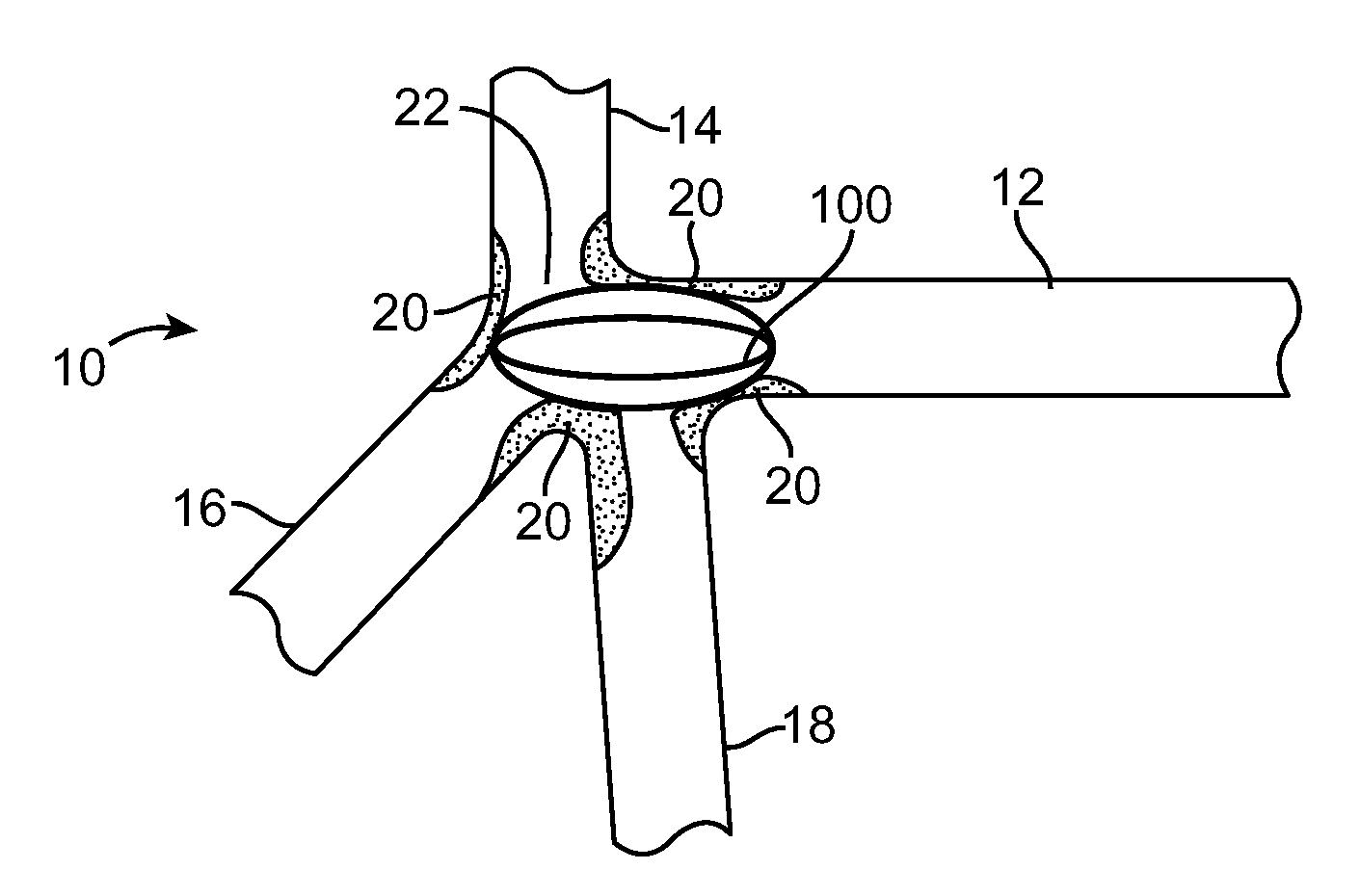
[0029]FIG. 1 shows a trifurcated vessel 10 including a first vessel branch 12, a second vessel branch 14, a third vessel branch 16, and a fourth vessel branch 18. Lesions 20 located at a junction 22 reduce blood flow, possibly leading to cardiac arrest. Lesions 20 located at junction 22 are difficult to stent using conventional, tubular bifurcated stents. Although a trifurcated vessel 10 is shown in FIG. 1, those of skill in the art would recognize that the vessel could be a bi...


PUM


Abstract

A stent for treating a region of a body lumen wherein at least two vessels form a junction includes a compressed state and an expanded state. In the expanded state, the stent is generally an ellipsoidal, spheroidal, or spherical shape. The stent is delivered to the junction in the compressed state disposed within a sleeve. Once at the junction, the sleeve is withdrawn proximally relative to the stent such that the stent is released from the sleeve and expands to the expanded state. A balloon may further expand the stent to appose the walls of the body lumen at the junction.

Description

FIELD OF THE INVENTION[0001]The invention relates generally stents and grafts for supporting strictures or stenoses in the human body. More particularly, the invention relates to a stent or graft for treating site or sites at or near a bifurcation or trifurcation of a body lumen.BACKGROUND OF THE INVENTION[0002]Stents are generally cylindrical-shaped devices that are radially expandable to hold open a segment of a vessel or other anatomical lumen after implantation into the lumen. Various types of stents are in use, including expandable and self-expanding stents. Expandable stents generally are conveyed to the area to be treated on balloon catheters or other expandable devices. For insertion, the stent is positioned in a compressed configuration along the delivery device, for example crimped onto a balloon that is folded or otherwise wrapped about a guide wire that is part of the delivery device. After the stent is positioned across the lesion, it is expanded by the delivery device,...

Claims


Application Information

Patent Timeline
Patent Type & Authority Applications(United States)
IPC IPC(8): A61F2/84A61F2/82A61F2/06A61F2/86
CPCA61F2/856A61F2/86A61F2/95A61F2/954A61F2230/0076A61F2002/30242A61F2230/0071A61F2230/0008A61F2002/065
Inventor MOLONEY, NOREEN
Owner MEDTRONIC VASCULAR INC
Why Eureka
Try Eureka