Switched reluctance motor

a technology of reluctance motor and reluctance motor, which is applied in the direction of horology, magnetic circuit shape/form/construction, instruments, etc., can solve the problem of narrow air gap, and achieve the effect of preventing excessive output torque, reducing torque fluctuation, and increasing the minimum generation torqu

Active Publication Date: 2009-07-02
DENSO CORP
View PDF17 Cites 22 Cited by
  • Summary
  • Abstract
  • Description
  • Claims
  • Application Information

AI Technical Summary

Benefits of technology

[0019]It is therefore the first object of the present invention to provide an SR motor capable of suppressing torque fluctuation when a large current is given to a coil. The second object of the present invention is to provide an SR motor capable of increasing a minimum generation torque when a small current is given to the coil. And, the third object of the present invention is to provide an SR motor capable of preventing an excessive output torque from being generated when the large current is given to the coil.

Problems solved by technology

In addition, because the depths of the concavities are shallow as the facing area between the stator tooth and rotor tooth increases, the average air gap becomes narrow.

Method used


Image

  • Switched reluctance motor
  • Switched reluctance motor
  • Switched reluctance motor

Examples


Embodiment Construction

[0046]An SR motor includes a stator which has a plurality of stator teeth, and a rotor which has a plurality of rotor teeth. Rotation force is given to the rotor by a pair of the rotor teeth among the plurality of the rotor teeth magnetically attracted by a pair of the stator teeth among the plurality of the stator teeth. When the pair of the stator teeth magnetically attracting the pair of the rotor teeth is successively switched, the rotor rotates.

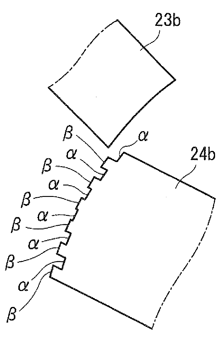
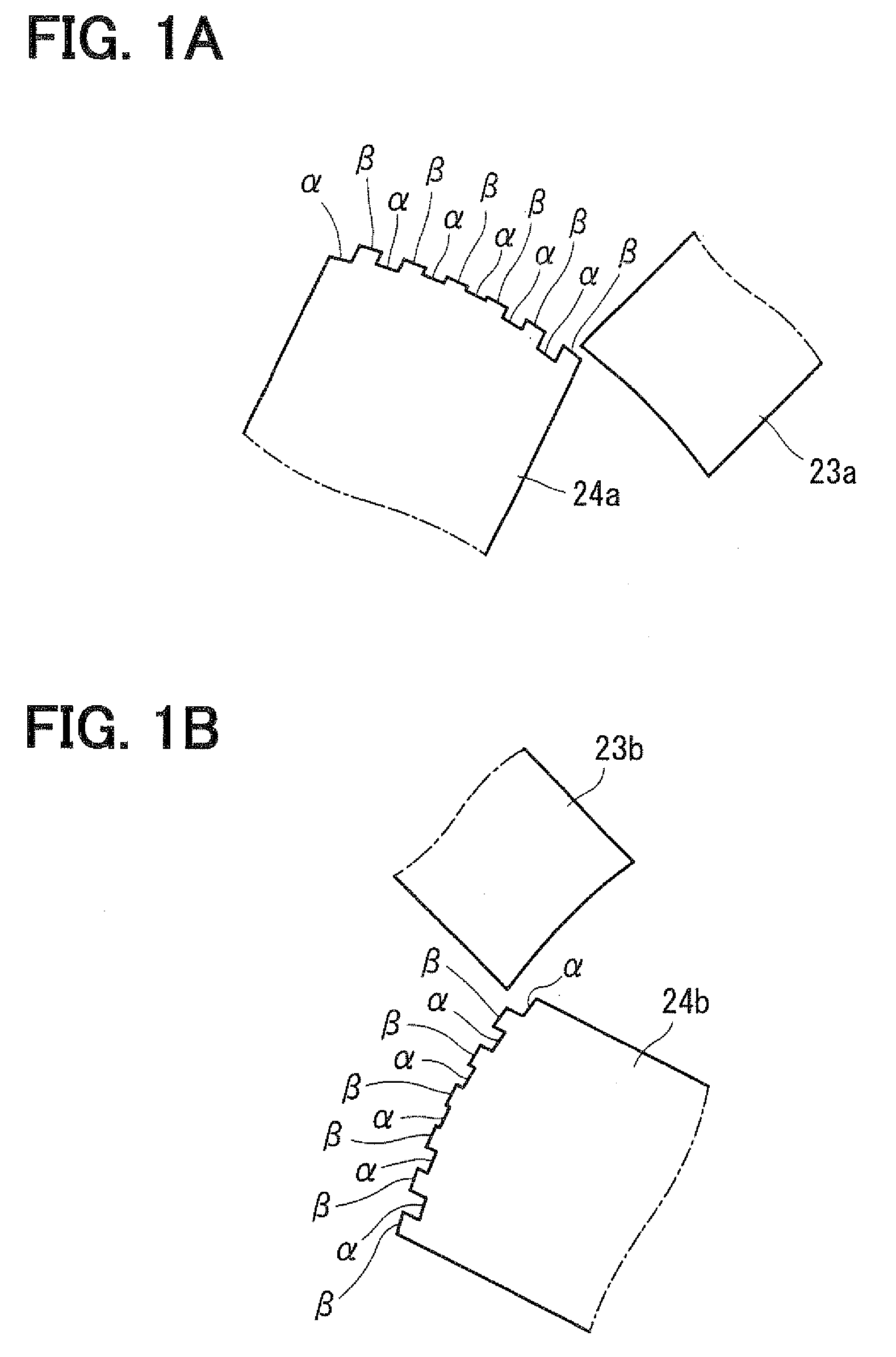
[0047]The SR motor according to the preferred embodiment has a plurality of concavities and convexities alternately formed at a tip of a rotor tooth or stator tooth along a rotation direction of the rotor. The depths of the concavities are deep on an edge side where the stator tooth and rotor tooth first approach when the rotor rotates and are shallow toward the direction in which a facing area of the stator tooth and rotor tooth increases. It is preferable that orders of the concavities and convexities formed in the pair of the rotor te...


PUM


Abstract

A plurality of concavities and convexities is provided on tips of all rotor teeth 24 of the SR motor 5. Depths of the concave portions α are deep on an edge side where a stator tooth 23 and rotor tooth 24 first approach and are shallow as a facing area between the stator tooth 23 and rotor tooth 24 increases. Therefore, magnetic resistance between the stator tooth 23 and rotor tooth 24 becomes high at an early stage of the stator tooth 23 and rotor tooth 24 facing each other and becomes low as the facing area between the stator tooth 23 and rotor tooth 24 increases. As a result, torque fluctuation can be suppressed at a time of a large current and a minimum generation torque can be increased at a time of a small current.

Description

CROSS REFERENCE TO RELATED APPLICATION[0001]This application is based on and claims priority from Japanese Patent Application No. 2007-337457 filed on Dec. 27, 2007, the contents of which are incorporated herein by reference.FIELD OF THE INVENTION[0002]This invention relates to a switched reluctance motor (hereinafter, referred to as an SR motor) usable as a rotary actuator.BACKGROUND OF THE INVENTION[0003]In recent years, an SR motor which is compact and has a high output torque has been used as, for example, an actuator for various systems mounted on a vehicle in many cases. One example in which the SR motor is used in a shift range switching apparatus (shift by wire: SBW) is described below.[0004]An automatic transmission of the vehicle has the shift range switching apparatus (including a parking switching mechanism). Although a driver manually shifted gear ranges formerly, the shift range switching apparatus in which an SBW actuator having the SR motor switches a shift range swi...

Claims


Application Information

Patent Timeline
Patent Type & Authority Applications(United States)
IPC IPC(8): H02K37/02
CPCH02K37/04
Inventor NAKAYAMA, SEIJIITOH, TAKUKIMURA, KIYOSHI
Owner DENSO CORP
Why Eureka
Try Eureka