Method for manufacturing quartz glass crucible

Inactive Publication Date: 2003-04-29
NANWA QUARTZ
View PDF2 Cites 48 Cited by
  • Summary
  • Abstract
  • Description
  • Claims
  • Application Information

AI Technical Summary

Benefits of technology

An object of the present invention is to provide a method of producing a silica glass crucible, in which: the number, the size, and the expansion ratio of the bubbles present in a transparent layer are made small such that explosion of the bubbles is prevented and the yield of the semiconductor single cry

Problems solved by technology

However, in the case of such new methods, a silica glass crucible of a large inside or inner diameter are often required.
When the inner diameter of the silica glass crucible is increased and a large amount of semiconductor materials are melted in the silica glass crucible, the melting time becomes longer and thus a longer time is required for entire pulling process.
However, when the amount of the inputted heat is large, the following undesirable outcomes may occur.
These bubbles tend to expand when the silica glass crucible is used at a high temperature, and the bubbles present in the transparent layer as the inner surface layer of the crucible, in particular, tend to explode as a result of increase in volume thereof.
The single crystal may then collapse from the portion at which the silica glass piece is deposited, thereby deteriorating the yield of the semiconductor single crystal.
This undesirable phenomenon becomes more significant when the amount of inputted heat is increased or the heat load is increased as the time required for the pulling process is prolonged, due to use of the silica glass crucible of a large inside diameter.
In the case of the method of producing a silica glass crucible disclosed in the former of the aforementioned two references, a problem, that the method may not be able to adapt to the current pulling process to a sufficient degree because the heat load is increased or the time required for the pulling process is prolonged due to use of a larger inner diameter of silicon single crystal or introduction of the "multi-pulling" process, may arise.
However, as the remaining gases (nitrogen gas or oxygen gas) are still not sufficiently replaced with the rapidly-diffusing gas in this production method, bubbles present in the opaque layer tend to increase volume thereof when the crucible is used (i.e., during the pulling process), thereby deteriorating the heat conductivity of the quartz crucible and thus raising t

Method used


Image

  • Method for manufacturing quartz glass crucible
  • Method for manufacturing quartz glass crucible
  • Method for manufacturing quartz glass crucible

Examples


first embodiment

The present invention will be described hereinafter according to the following embodiments. In a first embodiment, a means for reducing the number, the size and the expansion ratio of the bubbles present in a transparent layer formed in the inner surface of a silica glass crucible, is provided.

First, the number and the size of the bubbles are reduced by eliminating nitrogen gas, alkaline-earth metal and the like remaining between every particles of silica powder as the raw material, because such nitrogen gas, alkaline-earth metal and the like are the source of the air bubbles. More specifically, by introducing at least one of the gases selected from the group consisting of hydrogen, oxygen, water vapor, helium, neon gases and the like (when more than two types of gases are selected, the gases are introduced in the mixed state), a silica glass crucible having a relatively small number of the bubbles can be obtained. Such a silica glass crucible is obtained because the temperature ins...

second embodiment

In the second embodiment, oxygen gas is introduced together with the raw material powder through the inner cylinder of the double-wall cylinder and hydrogen gas is introduced through the outer cylinder. However, this structure may be constructed in a reversed manner. That is, hydrogen gas may be introduced together with the raw material powder through the inner cylinder and oxygen gas may be introduced through the outer cylinder. Further, the present embodiment is not limited to the structure in which oxygen gas and hydrogen gas are introduced separately. Both gases may be mixed in advance, so that the mixed gas is introduced.

Next, a production method for stabilizing the heat conductivity in the outer surface layer or the opaque layer of the silica glass crucible will be described. In order to make the heat conductivity of the opaque layer stable, helium gas is introduced from the pot or the mold for melting the silica powder and the gases in the voids of the silica powder accumulat...

third embodiment

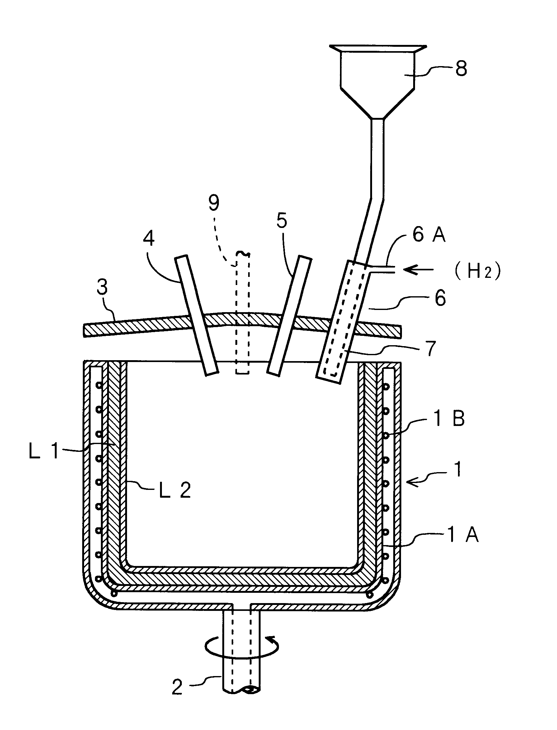
FIG. 6 is a sectional view of main portions of a production device which is used in the method for producing a silica glass crucible according to a The same reference numbers as in FIG. 1 are designated to the portions of FIG. 6 which are the same as or equivalent to FIG. 1. The end portion of a cooling water pipe 1B fixed to an inner wall 1A of the hollow portion of the mold 1, is extended downward the mold 1 and connected to a circulation device (not shown). Bores 10 for introducing helium as a replacing gas are formed at the bottom portion of the inner wall 1A of the mold 1. It should be noted that the bores 10 for introducing helium gas may be formed not only at the bottom portion but also at any positions between the bottom portion and the side wall of the mold 1 (refer to FIG. 9 which will be described later). The hollow portion of the double-wall mold 1 is filled with helium gas, which is supplied from the bottom portion of the mold 1. The helium gas filled in the hollow por...


PUM

PropertyMeasurementUnit
Timeaaaaaaaaaa
Pressureaaaaaaaaaa
Vacuumaaaaaaaaaa

Abstract

Present invention suppresses undesirable effects of the bubbles trapped in a silica glass crucible on single crystallization during the pulling process under a high-temperature load. When raw material powder is melted in a mold 1, graphite components of electrodes and impurities contained in the raw material are removed by introducing hydrogen gas and/or oxygen gas immediately after the start of arc discharge. Graphite and impurities are prevented from entering the product crucible, thereby suppressing the volume increase rate of the bubbles and reducing the inner pressure of the bubbles. Gases remaining in voids of an accumulated layer of silica powder formed inside the mold 1 can be replaced with helium gas, by supplying helium gas to the accumulated layer from the mold 1.

Description

The present invention relates to a method of producing a silica glass crucible, and especially to a method of producing a silica glass crucible which can improve the yield of semiconductor single crystal when used for pulling of semiconductor single crystal.As a method of producing semiconductor single crystal such as silicon single crystal, "the pulling method" (Czochralski method or CZ method), in which seed crystals as cores are immersed in a liquid surface of molten semiconductor materials such that single crystal is grown from the seed crystal, is known. A silica glass crucible is employed for melting semiconductor materials. In recent years, in order to reduce the production cost in the pulling process of single crystal, Multi-pulling method or large-diameter silicon single crystal pulling method has been attempted. However, in the case of such new methods, a silica glass crucible of a large inside or inner diameter are often required.When the inner diameter of the silica glas...

Claims


Application Information

Patent Timeline
IPC IPC(8): C03B19/00C03B19/09C30B15/10C30B35/00
CPCC03B19/095C30B35/002C30B15/10Y10S65/04Y02P40/57C03B20/00
Inventor AKIHO, KAZUHIROKUSUHARA, MASAKIWATANABE, HIROYUKIUNO, TOMOYASU
Owner NANWA QUARTZ
Why Eureka
Try Eureka