
Method and Apparatus for Imaging Utilizing an Ultrasonic Imaging Sensor Array

Inactive Publication Date: 2009-05-21
UNIV OF FLORIDA RES FOUNDATION INC
View PDF1 Cites 43 Cited by
  • Summary
  • Abstract
  • Description
  • Claims
  • Application Information

AI Technical Summary

Benefits of technology

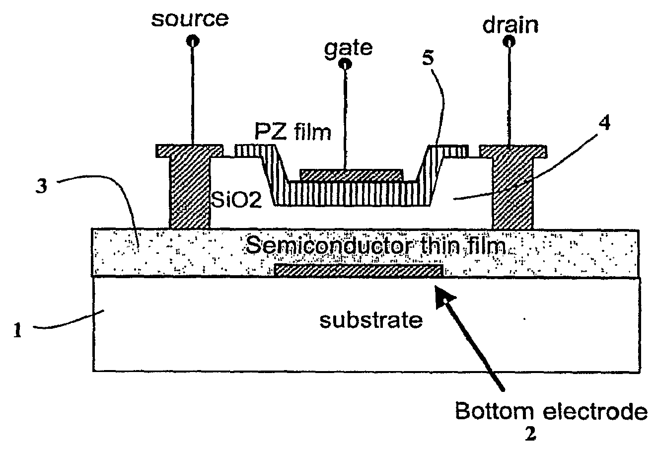
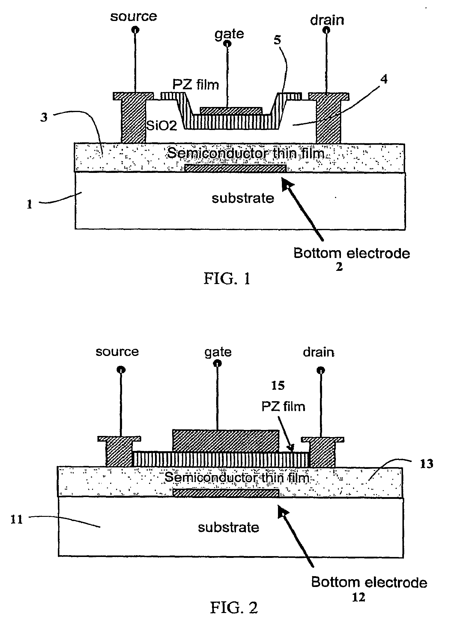
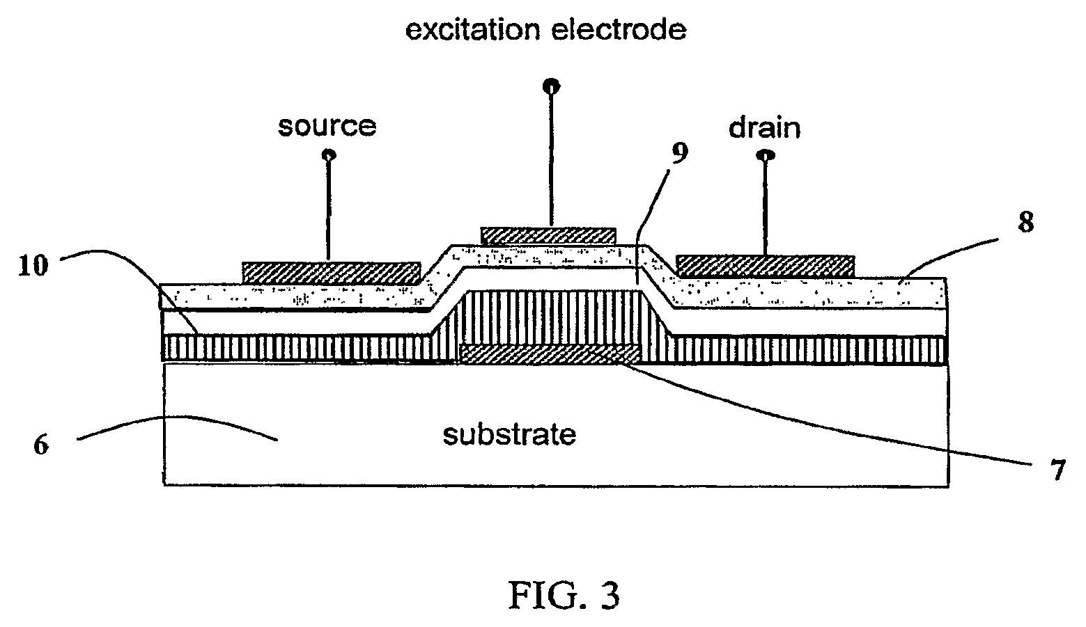
[0003]Embodiments of the subject invention pertain to a piezoelectric transducer device for improved acoustic wave sensing and / or generation. Embodiments of the invention relate to a process for making a piezoelectric transducer device. In an embodiment, a plurality of piezoelectric transducer devices can be used to form an array of piezoelectric transducers. Embodiments of the transducer array can eliminate the need for manual scanning, allow low cost fabrication, and / or enable high resolution imaging systems.

Problems solved by technology

This procedure can be tedious and time consuming, and often the image quality is poor.

Method used


Image

  • Method and Apparatus for Imaging Utilizing an Ultrasonic Imaging Sensor Array
  • Method and Apparatus for Imaging Utilizing an Ultrasonic Imaging Sensor Array
  • Method and Apparatus for Imaging Utilizing an Ultrasonic Imaging Sensor Array

Examples


Embodiment Construction

[0012]Embodiments of the subject invention pertain to a piezoelectric transducer device for improved acoustic wave sensing and / or generation. Embodiments of the invention relate to a process for making a piezoelectric transducer device. In an embodiment, a plurality of piezoelectric transducer devices can be used to form an array of piezoelectric transducers. Embodiments of the transducer array can eliminate the need for manual scanning, allow low cost fabrication, and / or enable high resolution imaging systems.

[0013]In one embodiment, a piezoelectric transducer can be a thin film transistor having a composite gate dielectric layer including a dielectric film and a piezoelectric film. The thin film transistor can be a thin film field effect transistor. In a specific embodiment, the gate dielectric layer can be a composite of a dielectric film such as SiO2 and a piezoelectric film. In another embodiment, a piezoelectric transducer can be a thin film transistor having a piezoelectric f...


PUM


Abstract

The subject invention pertains to a piezoelectric device structure for improved acoustic wave sensing and / or generation, and process for making same. The piezoelectric thin film field effect transducer can be a thin film transistor (TFT) with either a piezoelectric film gate or a composite gate having a dielectric film and a piezoelectric film. The TFT structure can be either a top gate device or a bottom gate device. In an embodiment, the piezoelectric device structure can be used to form an array of piezoelectric thin film field effect transducers. A TFT switch can drive each piezoelectric transducer in the array. The piezoelectric transducers can both generate and sense acoustic waves. In a sensing mode, a signal from an acoustic wave can be collected at a readout terminal of the piezoelectric transducer. In a generating mode, an excitation signal can be applied across the piezoelectric transducer while the switch is ‘on’.

Description

CROSS-REFERENCE TO RELATED APPLICATION[0001]The present application claims the benefit of U.S. Application Ser. No. 60 / 773,292, filed Feb. 14, 2006, which is hereby incorporated by reference herein in its entirety, including any figures, tables, or drawings.BACKGROUND OF INVENTION[0002]A conventional ultrasonic imaging system includes two elements: 1) an element that generates acoustic waves, and 2) a sensor that detects the reflected signals. In a typical ultrasonic imaging procedure, a probe is manually scanned across the imaging area. This procedure can be tedious and time consuming, and often the image quality is poor.BRIEF SUMMARY[0003]Embodiments of the subject invention pertain to a piezoelectric transducer device for improved acoustic wave sensing and / or generation. Embodiments of the invention relate to a process for making a piezoelectric transducer device. In an embodiment, a plurality of piezoelectric transducer devices can be used to form an array of piezoelectric trans...

Claims


Application Information

Patent Timeline
IPC IPC(8): H01L41/08
CPCH01L29/4908H01L27/20H10N39/00
Inventor SO, FRANKYNINO, JUAN CLAUDIO
Owner UNIV OF FLORIDA RES FOUNDATION INC
Learn More