Planar, high na, low loss transmitting or reflecting lenses using sub-wavelength high contrast grating
Active Publication Date: 2013-03-07
RGT UNIV OF CALIFORNIA
View PDF2 Cites 60 Cited by
Summary
Abstract
Description
Claims
Application Information
AI Technical Summary
This helps you quickly interpret patents by identifying the three key elements:
Problems solved by technology
Method used
Benefits of technology
Benefits of technology
This patent describes a new device called HCG-based planar lenses that can be used in optical imaging. These lenses are very small and can be easily integrated into optical circuits. They have high-contrast gratings that can focus light in both reflection and transmission. The gratings are designed to optimize energy distribution and minimize energy leakage. The lenses can provide double focusing with both the reflected and transmitted waves being focused. The invention also includes an optimization process to determine the position and width of the gratings. Overall, these lenses offer improved resolution and efficiency in optical imaging.
Problems solved by technology
Difficulties arise with integrating these optical lenses, and reflectors, requiring precisely curved surfaces and optical properties into devices, such as semiconductor devices, that may include vertical cavity surface emitting lasers (VCSEL) and the like.
Additionally, numerous problems arise with the thickness of conventional lenses and reflectors being integrated within optical devices.
Systems and devices in all these areas benefit from monolithic integration and the corresponding decreases in size, weight, and costs.
Because the lens must be transparent, the choice of material is limited and the highest refractive index is approximately two, which limits the NA of conventional lenses.
However, both the lens and reflector require an aspheric shape and bulky thickness, presenting difficulties for standard microfabrication techniques.
The major drawback of zone plates is that they absorb a significant part of the input power, making them undesirable for any optical application where low loss is required.
However, at the microscales necessary for device fabrication, the creation of Fresnel lenses becomes difficult.
So although high NA is achievable with a Fresnel lens, incorporating Fresnel lenses within integrated optics applications is problematic.
Method used
Image
Click on the blue label to locate the original text in one second.
Reading with bidirectional positioning of images and text.
Examples
embodiment 1
[0161]2. The apparatus of embodiment 1, wherein said high-contrast grating is planar.
[0162]3. The apparatus of embodiment 1, wherein said high-contrast grating is configured for high reflectivity, partial reflectivity, or high transmissivity.
[0163]4. The apparatus of embodiment 1, wherein said high-contrast grating is configured to allow selection of a wide range of phases while maintaining a certain reflectivity magnitude.
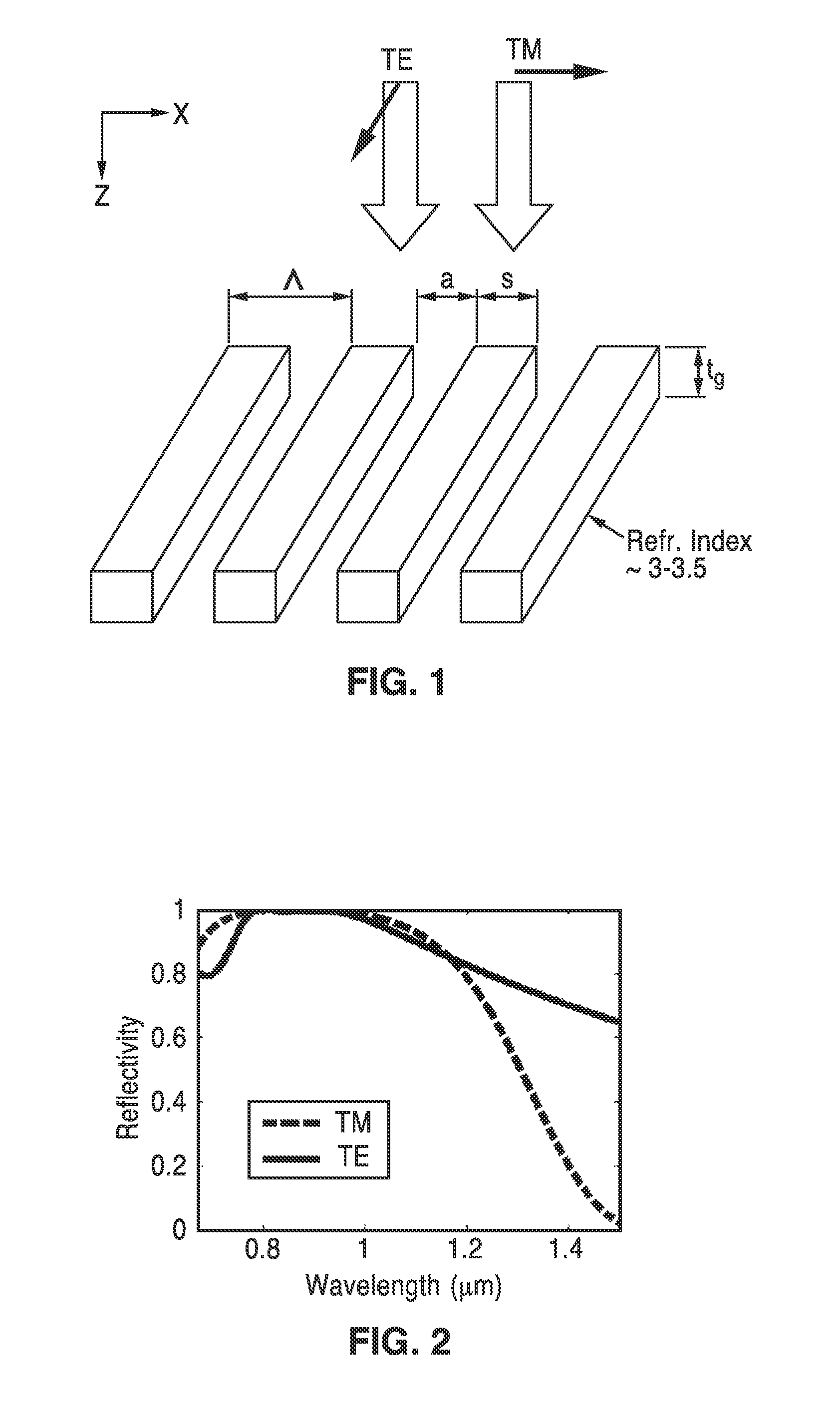
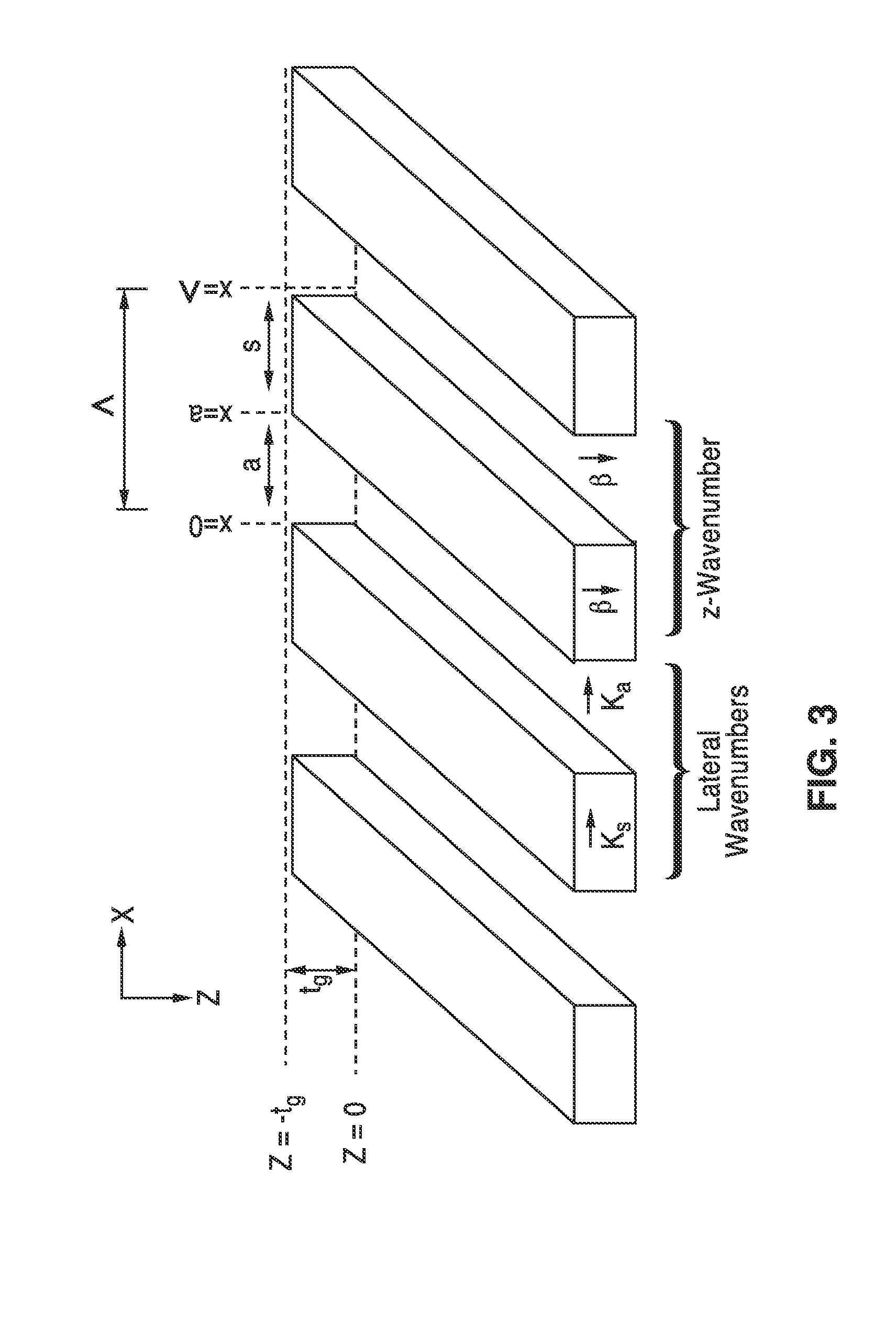
[0164]5. The apparatus of embodiment 1, wherein said high contrast grating comprises parallel bars of material having a high index of refraction and surrounded by a material having a low index of refraction.
[0165]6. The apparatus of embodiment 1, wherein said high contrast grating comprises curving bars of material having a high index of refraction and surrounded by a material having a low index of refraction.
embodiment 6
[0166]7. The apparatus of embodiment 6, wherein said high contrast grating comprises concentric circular bars of material having a high index of refraction and surrounded by a material having a low index of refraction.
[0167]8. The apparatus of embodiment 1, wherein said high contrast grating has grating elements whose spacing is varied along a distribution direction of said high-contrast grating elements to provide varying phase changes along a length of said high-contrast grating to focus said reflection and / or transmission.
[0168]9. The apparatus of embodiment 1, wherein the width of the high contrast grating bars vary along a distribution direction of the grating bars which is perpendicular to the length of the grating bars to focus said reflection and / or transmission.
[0169]10. The apparatus of embodiment 1, wherein both width and spacing of the high contrast grating bars vary along a distribution direction of the grating bars which is perpendicular to the length of the grating ba...
embodiment 15
[0176]17. The apparatus of embodiment 15, wherein said width and position of each grating element of said high contrast grating is further determined in response to a bar-by-bar optimization process in which the dimensions of each grating element (bar) is adjusted to minimize energy leakage to a transmission side for a reflector or a reflection side for a lens.
[0177]18. The apparatus of embodiment 1, wherein said high-contrast grating device is configured to provide double focusing with both the reflected and transmitted waves being focused.
[0178]19. An apparatus for focusing optical energy, comprising: a high-contrast grating (HCG) having grating elements spaced apart from one another; said high-contrast grating elements having subwavelength dimensions and an index of refraction at or exceeding approximately 2; and a low index of refraction material, or materials, surrounding said grating elements; wherein said grating is configured to receive an incident wave that is focused for r...
PUM
Abstract
Planar lenses and reflectors are described comprising subwavelength high-contrast gratings (HCG) having high index of refractiongrating elements spaced apart from one another in straight and / or curved segments and surrounded by low index material. The high-contrast grating is configured to receive an incident wave which excites multiple modes within the high-contrast grating and is focused for reflection and / or transmission by said high contrast grating. The width of the high contrast grating bars vary along a distribution direction of the grating bars which is perpendicular to the length of the grating bars and / or varies along the length of one or more grating bars to focus said reflection and / or transmission. The HCG is configured to provide double focusing, whose use is exemplified within a vertical cavity surface emitting laser (VCSEL) structure using focusing HCG structures for both the top and bottom mirrors.
Description
CROSS-REFERENCE TO RELATED APPLICATIONS[0001]This application a 35 U.S.C. §111(a) continuation of PCT international application number PCT / US2011 / 026112 filed on Feb. 24, 2011, incorporated herein by reference in its entirety, which is a nonprovisional of U.S. provisional patent application Ser. No. 61 / 307,843 filed on Feb. 24, 2010, incorporated herein by reference in its entirety, and a nonprovisional of U.S. provisional patent application Ser. No. 61 / 334,417 filed on May 13, 2010, incorporated herein by reference in its entirety. Priority is claimed to each of the foregoing applications.[0002]The above-referenced PCT international application was published as PCT International Publication No. WO 2011 / 106553 on Sep. 1, 2011 and republished on Jan. 19, 2012, and is incorporated herein by reference in its entirety.STATEMENT REGARDING FEDERALLY SPONSORED RESEARCH OR DEVELOPMENT[0003]This invention was made with Government support under Grant No. N00244-09-1-0013 awarded by the Depart...
Claims
Application Information
Patent Timeline
Application Date:The date an application was filed.
Publication Date:The date a patent or application was officially published.
First Publication Date:The earliest publication date of a patent with the same application number.
Issue Date:Publication date of the patent grant document.
PCT Entry Date:The Entry date of PCT National Phase.
Estimated Expiry Date:The statutory expiry date of a patent right according to the Patent Law, and it is the longest term of protection that the patent right can achieve without the termination of the patent right due to other reasons(Term extension factor has been taken into account ).
Invalid Date:Actual expiry date is based on effective date or publication date of legal transaction data of invalid patent.

