Pole mounted rotation platform and wind power generator

a technology of rotating platform and wind power generator, which is applied in the direction of ceilings, lighting support devices, and with built-in power, can solve the problems of large expanse of land, large investment, and rotor turning, and achieves small infrastructure development, flexible and scalable, and small entry cost.

Inactive Publication Date: 2011-05-12
IDEA LABS
View PDF22 Cites 49 Cited by
  • Summary
  • Abstract
  • Description
  • Claims
  • Application Information

AI Technical Summary

Benefits of technology

[0018]It is therefore desirable to provide a pole mounted rotation platform and wind power generator that requires very little infrastructure development and a relatively small entry cost.
[0019]It is further desirable to provide a pole mounted rotation platform and wind power generator that is flexible and scalable, yet environmentally friendly, and which can grow to meet the power demands of the future.
[0020]It is still further desirable to provide a pole mounted rotation platform and wind power generator that is economical to manufacture, market and maintain.
[0021]It is yet further desirable to provide a pole mounted rotation platform and wind power generator that can be used to generate clean

Problems solved by technology

Wind currently only produces a small percentage of our nation's electricity; however during the past twenty (20) years, the cost of wind energy has dropped dramatically, making it competitive with other energy sources.
When the wind blows, a pocket of low-pressure air forms on the downwind side of the blade; this low-pressure air pocket then pulls the blade toward it, resulting in lift and causing the rotor to turn.
Most wind turbines being used today are installed in wind farms, which require huge investments, expense

Method used


Image

  • Pole mounted rotation platform and wind power generator
  • Pole mounted rotation platform and wind power generator
  • Pole mounted rotation platform and wind power generator

Examples


Embodiment Construction

[0053]The devices and methods discussed herein are merely illustrative of specific manners in which to make and use the invention and are not to be interpreted as limiting in scope.

[0054]While the devices and methods have been described with a certain degree of particularity, it is to be noted that many modifications may be made in the construction and the arrangement of the structural and function details disclosed herein without departing from the spirit and scope of this disclosure. It is understood that the devices and methods are not limited to the embodiments set forth herein for purposes of exemplification.

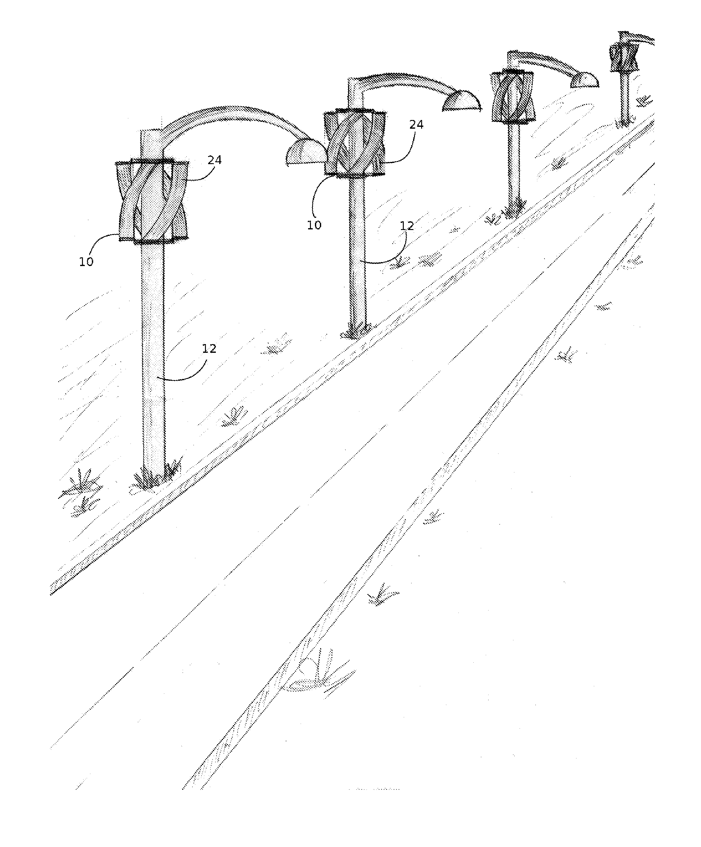
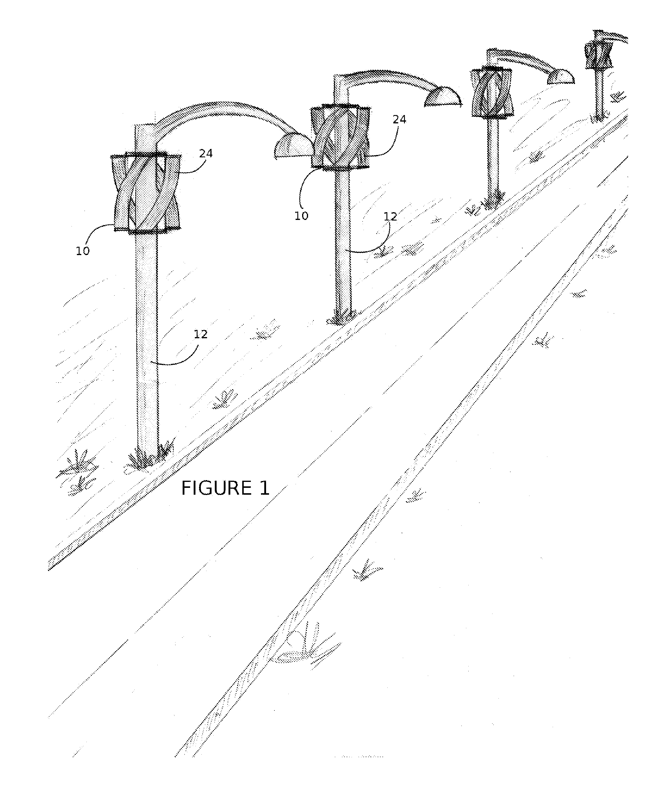
[0055]Referring to the figures of the drawings, wherein like numerals of reference designate like elements throughout the several views, and initially to FIG. 1, a pole mounted rotation platform and wind power generator 10 that is mountable to an existing structure 12, namely a light pole, a street light, a power transmission pole, a tower, an antenna, a building, a bridge ...


PUM


Abstract

A pole mounted rotation platform and wind power generator that is secured to an existing structure, which may or may not be vertical, to augment an existing power grid. The pole mounted rotation platform and wind power generator includes a wind sail assembly and a platform capable of rotating about the existing structure. The pole mounted rotation platform and wind power generator may be assembled, secured, leveled and aligned to the existing structure as component parts and in such a manner that any existing equipment on the existing structure does not need to be repositioned or relocated. During usage, the wind sail assembly rotates about the existing structure via the rotation platform, the resulting rotational energy is converted to electrical power, and the electrical power is output to a suitable power-using, -storing or -converting system.

Description

CROSS-REFERENCE TO RELATED APPLICATIONS[0001]This application claims priority to U.S. Provisional Application Ser. No. 61 / 247,788, filed Oct. 1, 2009, which is incorporated herein by reference.BACKGROUND OF THE INVENTION[0002]1. Field of the Invention.[0003]This invention relates generally to a pole mounted rotation platform and wind power generator, and more particularly to a pole mounted rotation platform and wind power generator capable of being mounted to an existing structure that may or may not be substantially, vertically oriented.[0004]2. Description of the Related Art.[0005]Wind is a source of clean, renewable energy. Utilization of wind energy reserves the earth's fossil fuels (e.g., coal, natural gas and oil) and alleviates the additional environmental impacts associated with burning fossil fuels. Wind, as a clean, efficient and abundant, never-ending resource, generates clean energy using the most up-to-date technologies available. Today, wind energy is the fastest-growi...

Claims


Application Information

Patent Timeline
IPC IPC(8): F03D11/04E04H14/00F03D11/00
CPCF03D9/00F03D11/04F05B2240/211F05B2240/212F21S9/043F05B2240/40F05B2240/913Y02B10/30Y02E10/728F05B2240/221F03D1/02F03D3/0409F03D9/255F03D13/20F03D80/70Y02E10/72Y02E10/74
Inventor FLORES, JUAN ESTEBAN
Owner IDEA LABS
Why Eureka
Try Eureka