Extendable virtual autoloader systems and methods

a virtual autoloader and extension technology, applied in the field of data storage devices, can solve the problems of increasing the cost of application upgrades, reducing the storage capacity of the device, and other limitations of prior art autoloader devices, etc., and achieves the effect of increasing storage capacity and low entry cos

Active Publication Date: 2006-05-18
TANDBERG DATA HLDG R L
View PDF12 Cites 20 Cited by
  • Summary
  • Abstract
  • Description
  • Claims
  • Application Information

AI Technical Summary

Benefits of technology

[0010] Embodiments of the invention provide a virtual cartridge autoloader system as a stand-alone system comprising an array of autoloaders. The system is typically rack-mounted with a capability for expansion to increase storage capacity. The system thus addresses desires of users who want systems that a physically small and manageable, with a low entry cost, but still having the ability to accommodate later increases in storage needs. The expandable design may start with a single autoloader acting as a master module, with expansion modules being electrically connected to the master module, and controlled as a single larger system. The individual autoloaders do not need to be physically stacked or even necessarily be in the same room, although in some embodiments where the system is rack mounted, the modules may physically be stacked one on top of another.

Problems solved by technology

Other types of prior art autoloader devices (e.g., optical autoloader devices) also have the same limitation.
Although these systems come in may different sizes and cartridge capacities, buyers may face a difficult dilemma when determining the capacity of the device that will best meet organizational requirements.
The first alternative is disruptive when the organization / application upgrades to a larger capacity device and more costly since two devices are purchased.
The second alternative has a high initial cost which may not be affordable or may be perceived to be unnecessary as larger capacity requirements may not be anticipated.

Method used


Image

  • Extendable virtual autoloader systems and methods
  • Extendable virtual autoloader systems and methods
  • Extendable virtual autoloader systems and methods

Examples


Embodiment Construction

[0039] In the following description, for the purposes of explanation, numerous specific details are set forth in order to provide a thorough understanding of the present invention. It will be apparent, however, to one skilled in the art that the present invention may be practiced without some of these specific details. In other instances, well-known structures and devices are shown in block diagram form.

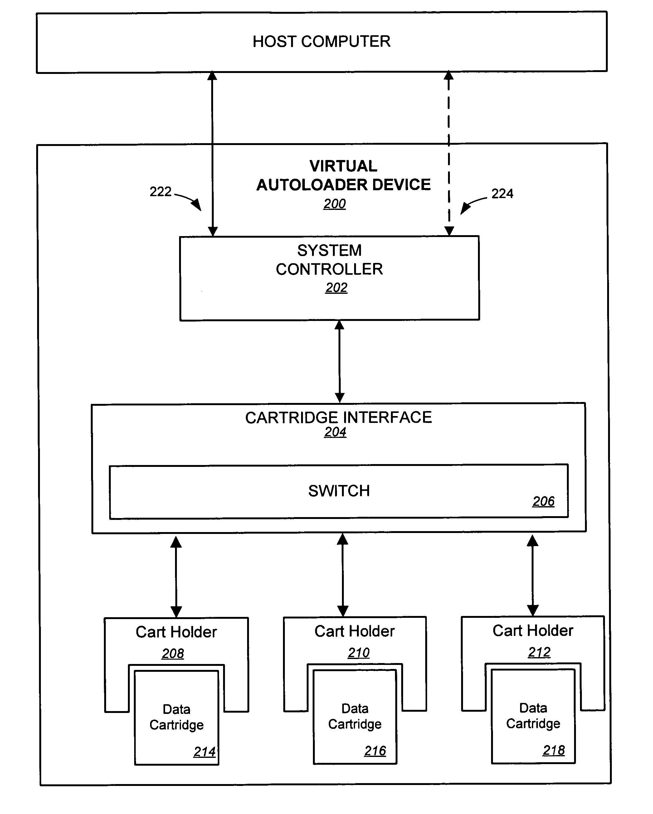
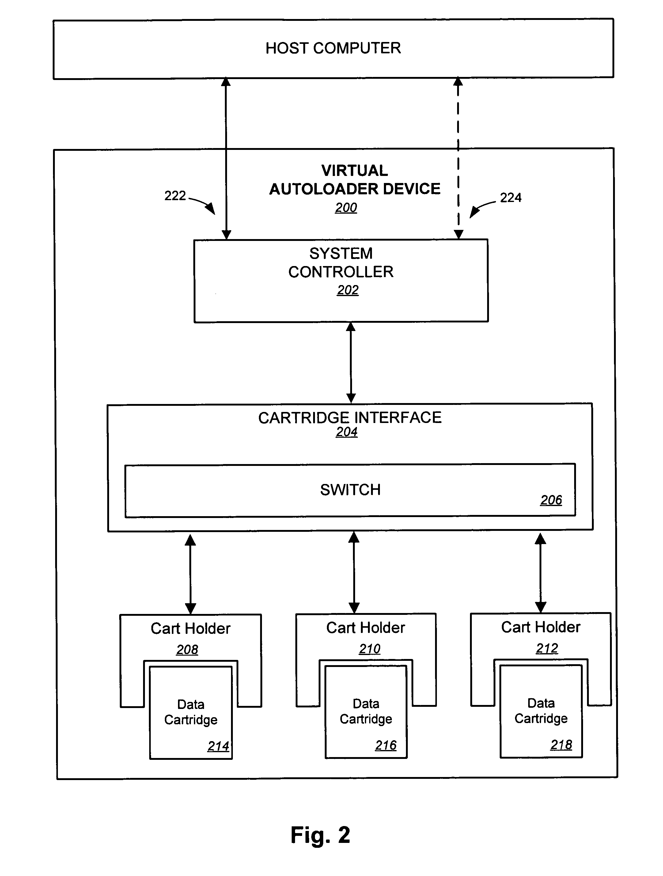
[0040]FIG. 2 illustrates an exemplary embodiment of a virtual autoloader device 200. The autoloader device 200 includes a system controller 202. System controller 202 may be used to manage communications and data transfers between autoloader device 200 and a host computer 220. Thus, system controller 202 may include one or more interfaces 222, 224 to host computer 220. By way of example, interface(s) to host computer may be Small Computer System Interface (SCSI), Fiber Channel (FC) interface, Ethernet interface, Advanced Technology Attachment (ATA) interface, or any other type of in...


PUM

PropertyMeasurementUnit
storage areaaaaaaaaaaa
mechanicalaaaaaaaaaa
movementaaaaaaaaaa

Abstract

A virtual cartridge autoloader system is provided. A first autoloader device has multiple cartridge holders. Each cartridge holder is configured for electrical communication with removable data cartridges having electronic interfaces. The first autoloader device performs virtual loading functions on the removable data cartridges using an electronic switch. A second autoloader device distinct from the first autoloader device is electrically interfaced with the first autoloader device. The second autoloader device also has multiple cartridge holders, each of which also is configured for electrical communication with removable data cartridges having electronic interfaces. The second autoloader device also performs virtual loading functions on the removable data cartridges using an electronic switch. A controller is configured to receive media changer commands from a host computer for the first autoloader device and for the second autoloader device. The autoloaders may thereby be operated as a single device.

Description

CROSS REFERENCE TO RELATED APPLICATION [0001] This application is a nonprovisional of, and claims the benefit of the filing date of, U.S. Prov. Pat. Appl. No. 60 / 629,012, entitled “EXTENDABLE VIRTUAL AUTOLOADER SYSTEMS AND METHODS,” filed Nov. 17, 2004 by Steven P. Georgis, the entire disclosure of which is incorporated herein by reference for all purposes.BACKGROUND OF THE INVENTION [0002] The present invention generally relates to data storage devices. More specifically, the present invention relates to removable cartridge storage devices. [0003] Computer backup has traditionally been performed using tape drive technologies. Tape drive technologies have been popular in the use of backup systems for a variety of reasons. One reason is that tape media has generally had the lowest cost per bit of storage. Additionally, tape devices use removable tape cartridges, which may be taken to an off-site location to provide for disaster recovery. A third reason tape devices are popular is bec...

Claims


Application Information

Patent Timeline
Patent Type & Authority Applications(United States)
IPC IPC(8): G11B19/02G11B15/12
CPCG11B15/6835G11B17/225
Inventor GEORGIS, STEVEN P.
Owner TANDBERG DATA HLDG R L
Why Eureka
Try Eureka