Mounting structure of electronic device and pneumatic tire

a technology of electronic devices and mounting structures, which is applied in the direction of tyre measurements, with separate inflatable inserts, without separate inflatable inserts, etc., can solve the problems of cumbersome repairing or changing the operation of electronic devices, and difficulty in keeping the electronic devices stably mounted over the long term

Inactive Publication Date: 2009-07-09
BRIDGESTONE CORP
View PDF6 Cites 32 Cited by
  • Summary
  • Abstract
  • Description
  • Claims
  • Application Information

AI Technical Summary

Benefits of technology

[0027]Further, it is preferable that two of the guide tabs extend a tire lateral direction opposingly. Since the two of the guide tabs extend the tire lateral direction opposingly, rattling of the electronic device, especially due to input forces at stop-spinning (speed-reducing) and start-spinning (speed-accelerating) of the pneumatic tire among the various input forces, can be restrained sufficiently.

Problems solved by technology

Therefore, the electronic device may be easy to rattle due to various input forces (external forces) during the pneumatic tire spinning, thereby it is difficult to keep the electronic device stably-mounted over the long term.
However, in this case, the electronic device is hard to be removed from the inner liner, thereby the repairing or changing operation of the electronic device becomes cumbersome.

Method used


Image

  • Mounting structure of electronic device and pneumatic tire
  • Mounting structure of electronic device and pneumatic tire
  • Mounting structure of electronic device and pneumatic tire

Examples


first embodiment

[0042]A first embodiment according to the present invention will be explained with reference to FIGS. 1 to 5.

[0043]As shown in FIG. 5, a pneumatic tire 1 in the first embodiment can be filled with air as working gas and has a pair of annular bead fillers 5 capable of being tightly seated on a rim 3. A bead core 7 is mounted within each of the bead fillers 5. In addition, a carcass 9 is integrally provided between the pair of bead fillers 5 as a structural member. This carcass 9 has a troidal cross-sectional shape. Further, a multiply belt 11 is integrated on an outer circumferential surface of the carcass 9.

[0044]A tread 13 surrounding the belt 11 is integrally provided on the outer circumferential surface of the carcass 9. Sidewalls 15 for protecting the carcass 9 are integrally provided on outer side surfaces of the carcass 9. In addition, an inner liner 17 for preventing air permeation is also integrally provided on an inner surface (incl. an inner circumferential surface).

[0045]...

second embodiment

[0059]A second embodiment according to the present invention will be explained with reference to FIGS. 6 to 11.

[0060]As shown in FIG. 11, a pneumatic tire 41 in the second embodiment has a pair of bead fillers 5, bead cores 7, a carcass 9, a multiply belt 11, a tread 13, side walls 15 and an inner liner 17, similarly to the first embodiment. Note that, among plural components of the pneumatic tire 41 in the second embodiment, components correspondent to those of the pneumatic tire 1 in the first embodiment are allocated with the identical numbers in the drawings to omit their explanations.

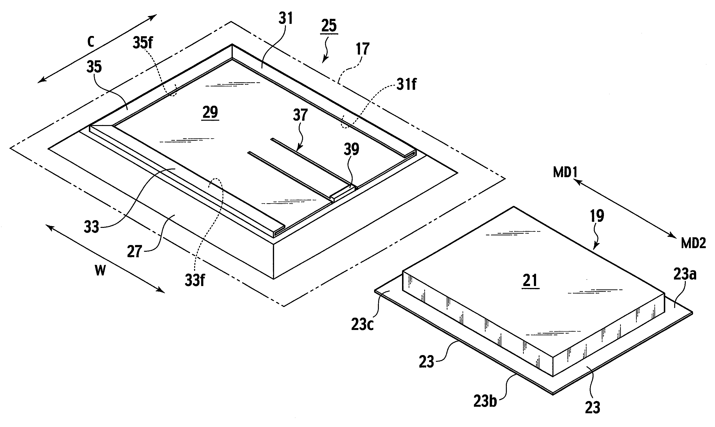
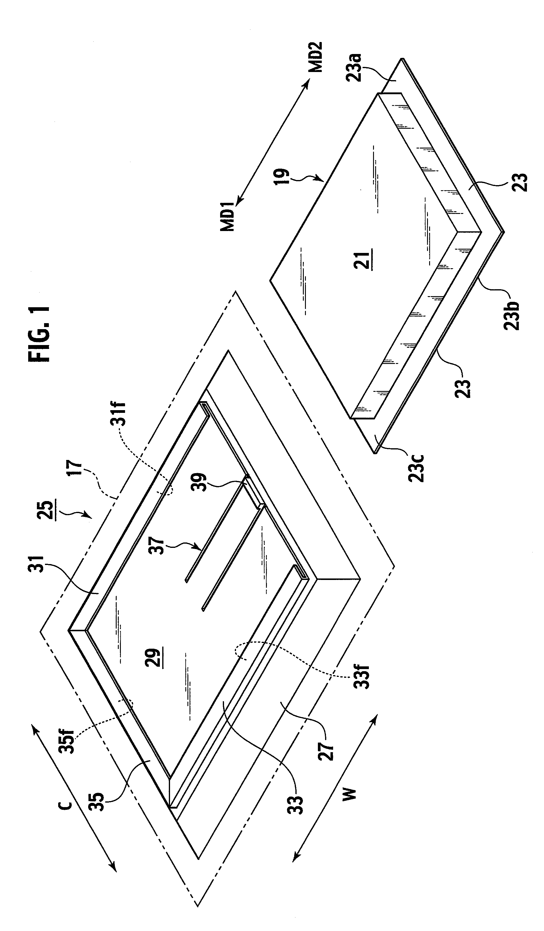
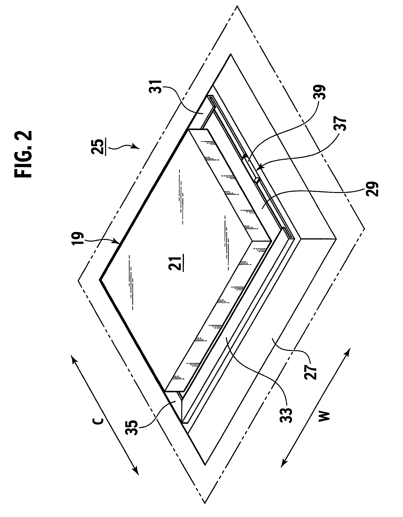
[0061]As shown in FIG. 6, a transponder 43 is mounted on an inner circumferential surface of the inner liner 17. The transponder 43 includes a box-shaped electronic device main body 45 that incorporates various electronic components (not shown). In addition, a circular device plate 47 is provided at a bottom of the electronic device main body 45, which is composed of light alloy metal such as alumi...


PUM


Abstract

A electronic device is mounted on a circumferential surface of an inner liner by tucking first, second and third edges of a device plate between a first holding plane of a first guide tab and a surface of a holder plate, between a second holding plane of a second guide tab and the surface of the holder plate, and between a third holding plane of a third guide tab and the surface of the holder plate. The electronic device can be stably-mounted over the long term without difficulty and can be removed from the circumferential surface of the inner liner without difficulty.

Description

TECHNICAL FIELD[0001]The present inventions relate to a mounting structure of an electronic device for attaching the electronic device such as a transponder and an inner pressure monitoring device on an inner liner of a pneumatic tire, and to a pneumatic tire on which the electronic device is attached with the mounting structure of an electronic device.BACKGROUND ART[0002]A Patent Document 1 shows a prior art of a mounting structure of an electronic device for mounting the electronic device such as a transponder on an inner liner of a pneumatic tire. A specific structure according to this prior art of a mounting structure of an electronic device will be explained hereinbelow.[0003]Specifically, a rubber base (a rubber ply (130) in the Patent Document 1) is fixed on the inner liner. A mounting shaft (a shaft (152) in the Patent Document 1) is integrally provided on the center of the rubber base. A mounting head (a head of the shaft (152) in the Patent Document 1) is integrally provid...

Claims


Application Information

Patent Timeline
Patent Type & Authority Applications(United States)
IPC IPC(8): B60C23/04B60C19/00
CPCB60C23/0493
Inventor UTSUMI, ATSUOWATANABE, YOICHIFURUKAWA, MAKOTOICHIKAWA, YOSHIHIKO
Owner BRIDGESTONE CORP
Why Eureka
Try Eureka