Connecting structure of connector, shield connector and lever type connector

Active Publication Date: 2006-08-01
AUTONETWORKS TECH LTD +2
View PDF5 Cites 22 Cited by
  • Summary
  • Abstract
  • Description
  • Claims
  • Application Information

AI Technical Summary

Benefits of technology

[0028][Operation and Effect of the Invention]
[0029][First Aspect of the Invention]
[0030]In integrating the two connectors, the shield shells may be fitted to each other simultaneously with fitting the housings and therefore, the fitting can be carried out by operation in one action. Further, a portion of fitting the shield shells is shielded by a double structure overlapped inside and outside and therefore, a high shielding effect is achieved. Further, by making the shield shell by diecasting, strength of the shield shell can be increased.
[0031][Second and Sixth Aspects of the Invention]
[0032]Although the inner periphery of the shield shell needs to form in a taper shape in order to smoothly draw the die for diecastin

Problems solved by technology

However, according to the shield connector, operation of attaching the wire side terminals to the attaching holes and operation of connecting the shield members to the shield case need to repeat respectively by a number of times the same as a number of poles of the terminals (that is, number of pieces of shield wires) and therefore, there p

Method used


Image

  • Connecting structure of connector, shield connector and lever type connector
  • Connecting structure of connector, shield connector and lever type connector
  • Connecting structure of connector, shield connector and lever type connector

Examples


Example

[0075]An explanation will be given of an embodiment of the invention with reference to FIG. 1 through FIG. 17 as follows.

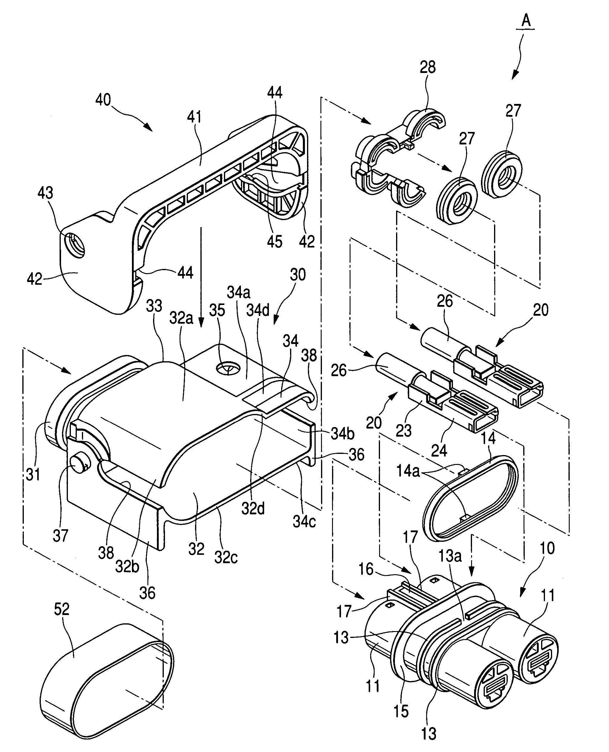
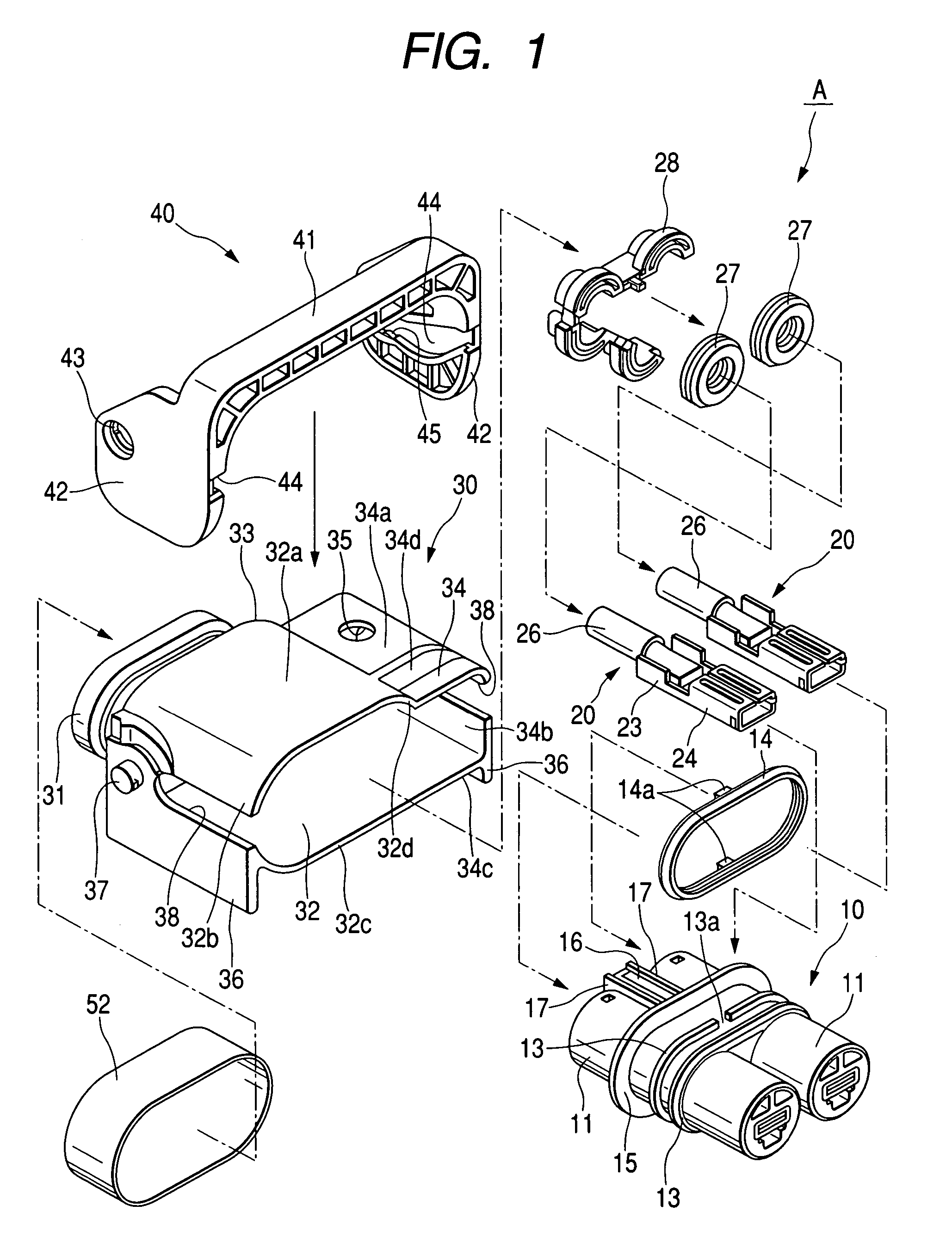
[0076]According to this embodiment, an explanation will be given of a shield connector (hereinafter, referred to as first connector A) and a structure of fitting and detaching the shield connector and a counter side connector (hereinafter, referred to as second connector B). A lever type connector according to this embodiment is constituted by a first connector A and a second connector B which can be fitted to each other and separated from each other.

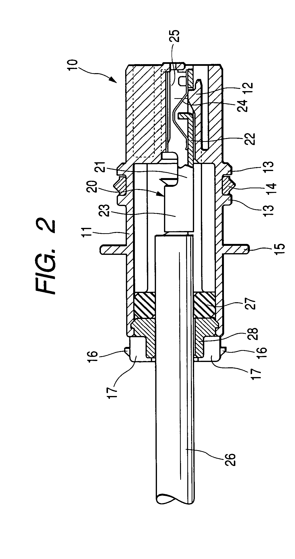
[0077]The first connector A is constituted by mainly including a first housing 10, a pair of left and right first terminal metal pieces 20, and a first shield shell 30. The first housing 10 is made of a synthetic resin and a pair of left and right terminal containing portions 11 substantially constituting a cylindrical shape and penetrated in a front and rear direction are connected to constitute an integral part, and...


PUM


Abstract

A connecting structure of a connector includes: a first connector having a housing for containing a plurality of terminal metal pieces connected to a plurality of wires, a shield shell including a hood portion projected to a front side and surrounding the housing, and a shield member connected with the shield shell and surrounding the plurality of the wires; and a second connector capable of being fitted to the first connector, the second connector having a housing capable of containing a plurality of terminal metal pieces and capable of being fitted to the housing of the first connector and a shield shell surrounding the housing. At least one of the shield shell of the first connector and the shield shell of the second connector is made by diecasting.

Description

BACKGROUND OF THE INVENTION[0001]1. Field of the Invention[0002]The present invention relates to a connecting structure of a connector, a shield connector and a lever type connector.[0003]2. Description of the Related Art[0004]There is a shield connector for connecting a plurality of pieces of shield wires to an apparatus of an inverter apparatus or the like in, for example, an electric car having a structure for providing apparatus side terminals at inside of a shield case of the apparatus, opening attaching holes in correspondence with the respective apparatus side terminals at the shield case, respectively inserting wire side terminals fixedly attached to distal ends of the respective shield wires into the attaching holes to connect to the apparatus side terminals, and respectively connecting distal end portions of shield members of the respective shield wires to the shield case (refer to, for example, JP-A-11-26093).[0005]Conventionally, there is a lever type connector in which ...

Claims


Application Information

Patent Timeline
IPC IPC(8): H01R9/03H01R13/52H01R13/629H01R13/658
CPCH01R13/5221H01R13/6593H01R13/62933
Inventor HAYASHI, HIROYUKI
Owner AUTONETWORKS TECH LTD
Why Eureka
Try Eureka