Electromechanical transducer and method of manufacturing the same

Inactive Publication Date: 2011-06-16
CANON KK
View PDF14 Cites 10 Cited by
  • Summary
  • Abstract
  • Description
  • Claims
  • Application Information

AI Technical Summary

Benefits of technology

[0009]According to the present invention, where the outer side walls of the first electrodes separated from one another by the grooves are covered with the insulating films, a foreign object entering one of the grooves which are gaps is prevented from causing a short circuit between the first electrodes adjoined to the groove. In addition, the width between the insulating films on the opposing outer side walls of every two adjacent first electrodes is narrower on the groove opening side (i.e., the side of the second face of the substrate wh

Problems solved by technology

However, with a conventional CMUT that has a groove for separating one lower electrode from another as described above, there is a possibility of a conductive foreign o

Method used


Image

  • Electromechanical transducer and method of manufacturing the same
  • Electromechanical transducer and method of manufacturing the same
  • Electromechanical transducer and method of manufacturing the same

Examples


first embodiment

[0016

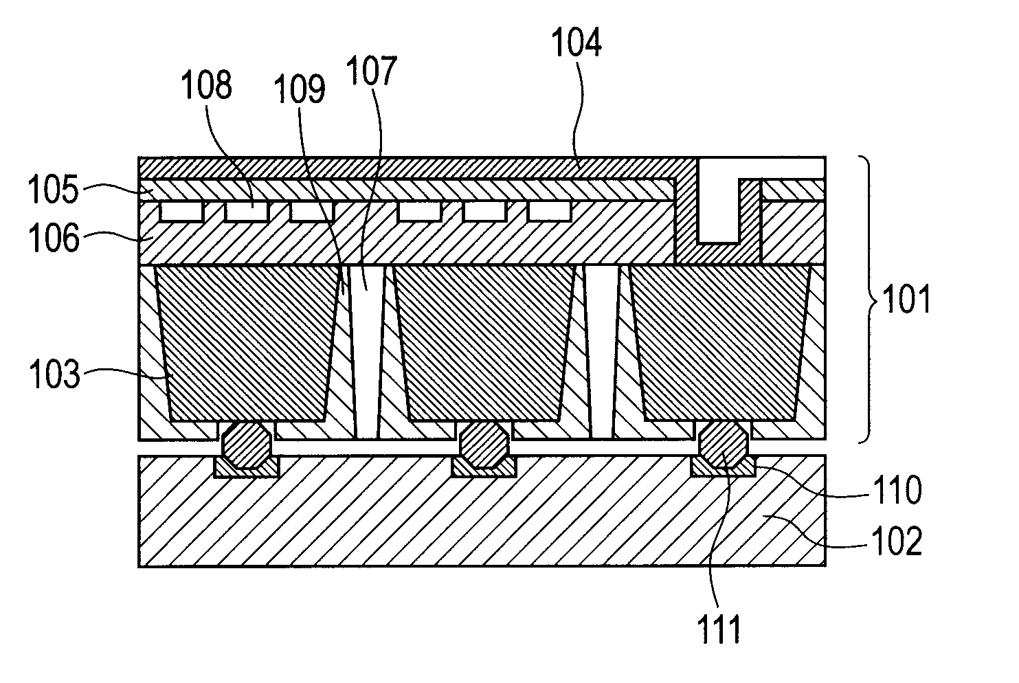
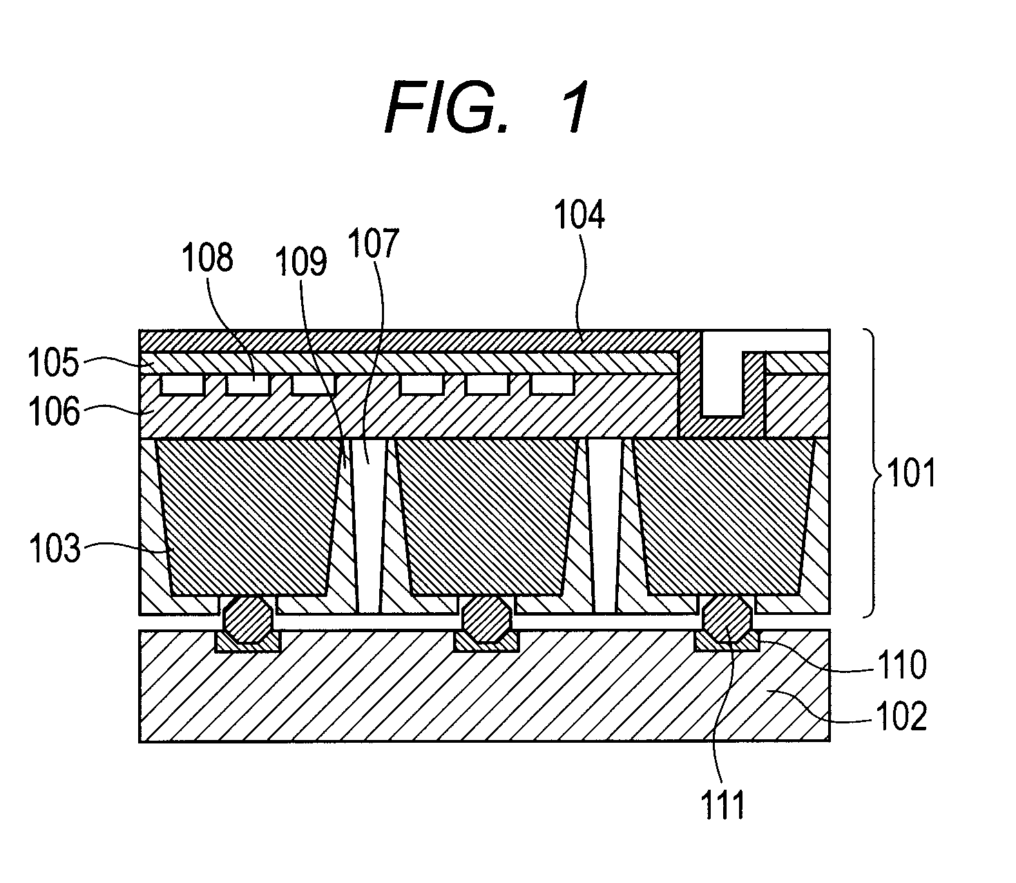
[0017]The first embodiment deals with a capacitive micromachined ultrasound transducer (CMUT) as an electromechanical transducer to which the present invention can be applied. However, the present invention is applicable not only to CMUTs but also to any electromechanical transducers that have a similar structure (a structure in which a substrate is divided by grooves to form first electrodes of the respective elements). For example, the present invention is applicable to ultrasonic transducers that use distortion, a magnetic field, or light (piezoelectric micromachined ultrasound transducers (PMUTs), magnetic micromachined ultrasound transducers (MMUTs), and the like). In other words, electromechanical transducers to which the present invention can be applied are not limited to those whose lower electrodes 103 (first electrodes) to be described later are structured as below.

[0018]As illustrated in FIG. 1, which is a schematic diagram illustrating the sectional structure of the...

second embodiment

[0025

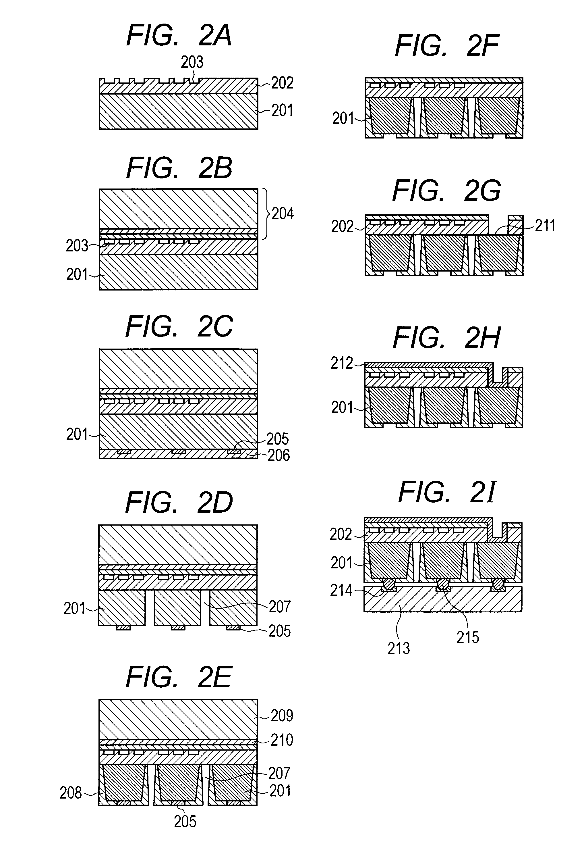
[0026]The second embodiment deals with a method of manufacturing a CMUT as an electromechanical transducer to which the present invention can be applied. According to the manufacturing method of this embodiment, a CMUT is manufactured as follows. A Si substrate is prepared in which grooves separate lower electrodes of respective elements from one another, and insulating films are formed on lower electrode surfaces that face the grooves. An SOI substrate is bonded onto the Si substrate to form a membrane, and the lower electrodes are wired to a circuit board. The insulating films on the outer side walls of the lower electrodes separated from one another by the grooves are formed by thermal oxidation.

[0027]By thermally oxidizing the lower electrodes, oxide films are formed on the outer side walls of the lower electrodes to be thicker toward the groove opening side, and a device form in which the groove width is narrower toward the groove opening side is obtained easily. An oxide ...


PUM


Abstract

An electromechanical transducer includes: a conductive substrate; multiple elements which are disposed on a first face side of the substrate and which contain cells; grooves; and insulating films. The substrate has a second face which is opposite from the first face. The grooves run from the second face of the substrate to the first face of the substrate in a manner that electrically isolate the multiple elements from one another, thereby dividing the substrate and forming first electrodes. The insulating films are formed on opposing outer side walls of every two adjacent first electrodes across one of the grooves. The width between the insulating films is narrower on the second face side of the substrate than on the first face side of the substrate. The insulating films are thicker on the second face side than on the first face side.

Description

BACKGROUND OF THE INVENTION[0001]1. Field of the Invention[0002]The present invention relates to an electromechanical transducer such as an ultrasonic transducer, and to a method of manufacturing the electromechanical transducer. More specifically, the present invention relates to a technology of improving the reliability of an electromechanical transducer.[0003]2. Description of the Related Art[0004]Ultrasonic transducers perform conversion from an electrical signal to an ultrasonic wave and conversion from an ultrasonic wave to an electrical signal, and are used, among others, as probes for medical imaging or non-destructive inspection. One form of ultrasonic transducer is a capacitive micromachined ultrasound transducer (CMUT). A CMUT generally includes a substrate, which has a lower electrode, a membrane, which is supported to the substrate by a supporting portion formed on the substrate, and an upper electrode. The CMUT uses a voltage applied between the lower electrode and the...

Claims


Application Information

Patent Timeline
IPC IPC(8): H01L29/84H01L21/02
CPCB06B1/0292G01N29/2406G01N29/0654
Inventor ITOH, HIDEYUKIEZAKI, TAKAHIRO
Owner CANON KK
Why Eureka
Try Eureka