Side window roller blind with insertion aid

Active Publication Date: 2009-03-26
BOS
View PDF9 Cites 21 Cited by
  • Summary
  • Abstract
  • Description
  • Claims
  • Application Information

AI Technical Summary

Benefits of technology

[0006]In view of the foregoing, a general object of the present invention

Problems solved by technology

Any diagonal creases in the blind are perceived to be particularly unattractive.
A conical winding shaft can also raise problems with known arrangements.
Other problems with side

Method used


Image

  • Side window roller blind with insertion aid
  • Side window roller blind with insertion aid
  • Side window roller blind with insertion aid

Examples


Example

[0033]While the invention is susceptible of various modifications and alternative constructions, a certain illustrative embodiment thereof has been shown in the drawings and will be described below in detail. It should be understood, however, that there is no intention to limit the invention to the specific form disclosed, but on the contrary, the intention is to cover all modifications, alternative constructions, and equivalents falling within the spirit and scope of the invention.

DESCRIPTION OF THE PREFERRED EMBODIMENTS

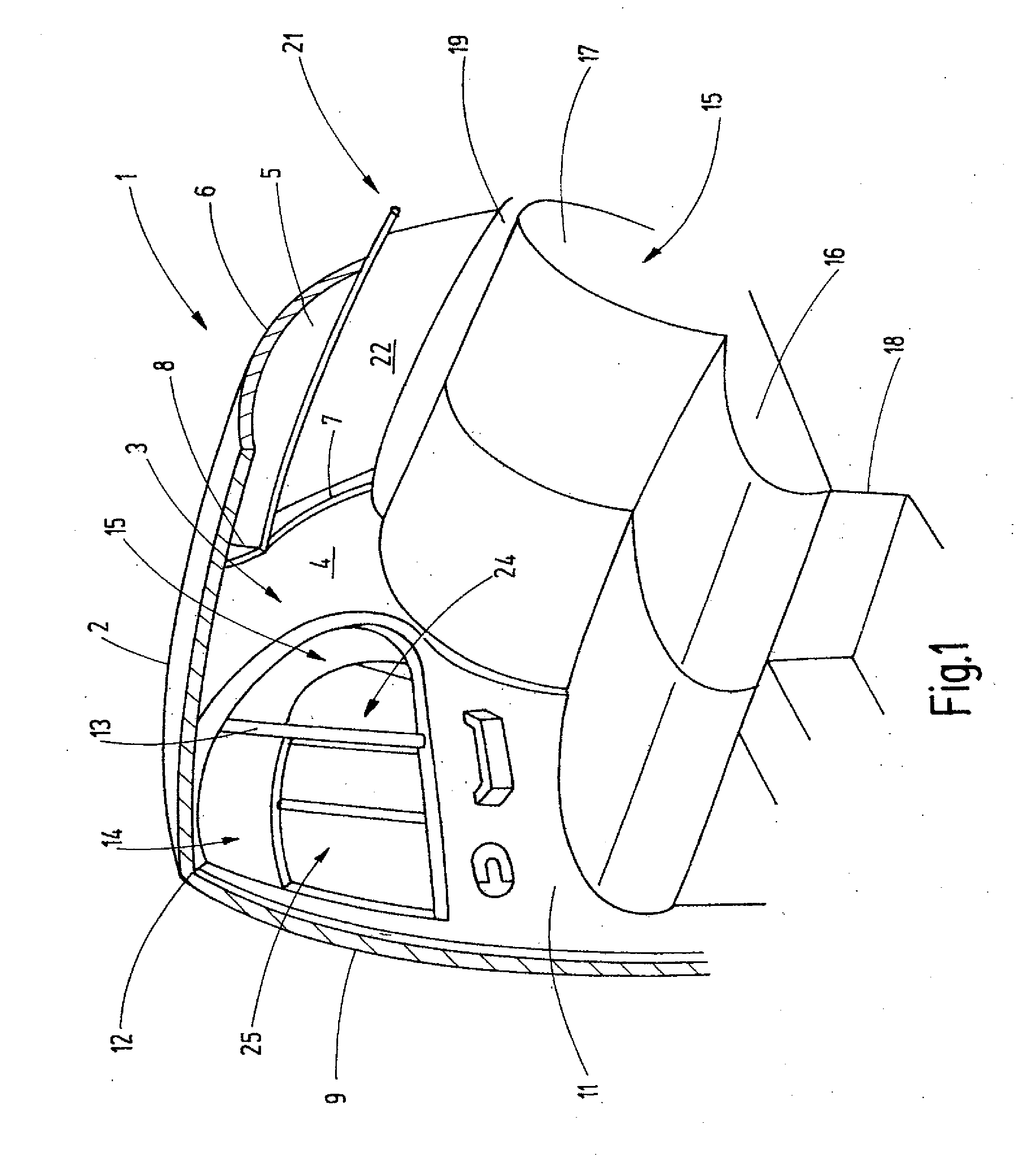
[0034]Referring to FIG. 1 of the drawings, the passenger area of an exemplary motor vehicle is shown. The right side of the passenger area is shown in FIG. 1 and it is a mirror image of the left inner side. If not indicated otherwise, the explanations concerning the right side of the car body also apply to the left side of the car body. FIG. 1 is simplified in that, for example, interior car body structures such as reinforcements and mounting elements are not shown ...


PUM


Abstract

A side window roller blind is provided. The roller blind includes a support rod having a free end connected to a tension bar. In order to prevent rattling noises, the ends of the tension bar are provided with rollers that contact the window pane such that the support rod is elastically bent during extension of the blind. In addition, the window blind is provided with aligning aids that prevent the tension bar from hitting on the slot edges during retraction of the blind, and from blocking additional retraction, due to vibrations about the longitudinal axis of the tension bar.

Description

CROSS-REFERENCE TO RELATED APPLICATIONS[0001]This patent application claims the benefit of German Patent Application No. 102007045414.9, filed Sep. 21, 2007 which is incorporated herein by reference.FIELD OF THE INVENTION[0002]The present invention relates generally to roller blinds for windows of motor vehicles.BACKGROUND OF THE INVENTION[0003]Modern side window roller blinds for motor vehicles attempt to conceal the guide elements for guiding the blind whenever possible. This means that conventional guide rails that extend beside the rectangular part of the window need to be replaced with guide or support rods. As their name implies, the support rods support the tension bar arranged on the free edge of the blind when the blind is extended. This means that the support rods have two functions, namely guiding the tension bar such that it remains on the window and generating the required thrust for unwinding the blind from the winding shaft and maintaining the blind in the stretched s...

Claims


Application Information

Patent Timeline
IPC IPC(8): B60J1/20E06B9/42B60J3/02
CPCB60J1/2086B60J1/2033B60J1/2013B60J1/2041B60J1/205B60J1/2063B60J3/005B60J3/02B60Y2200/11
Inventor HANSEN, MELF
Owner BOS
Why Eureka
Try Eureka