
Inside door handle device of automobile

a technology for inside door handles and automobiles, which is applied in the direction of carpet fasteners, lock applications, wing knobs, etc., can solve the problems of incongruity in the design the appearance of the inside handle device is ugly, and the above-conventional example is disadvantageous, so as to prevent the rattle of the cover body and the beauty of the handle device. the effect of a few dents

Inactive Publication Date: 2006-09-12
ALPHA
View PDF6 Cites 22 Cited by
  • Summary
  • Abstract
  • Description
  • Claims
  • Application Information

AI Technical Summary

Benefits of technology

[0004]The present invention has been accomplished to solve the above problems of the prior art. It is an object of the present invention to provide an inside door handle device of an automobile capable of enhancing a sense of beauty by completely covering a fixing portion of the inside door handle device to a vehicle body.
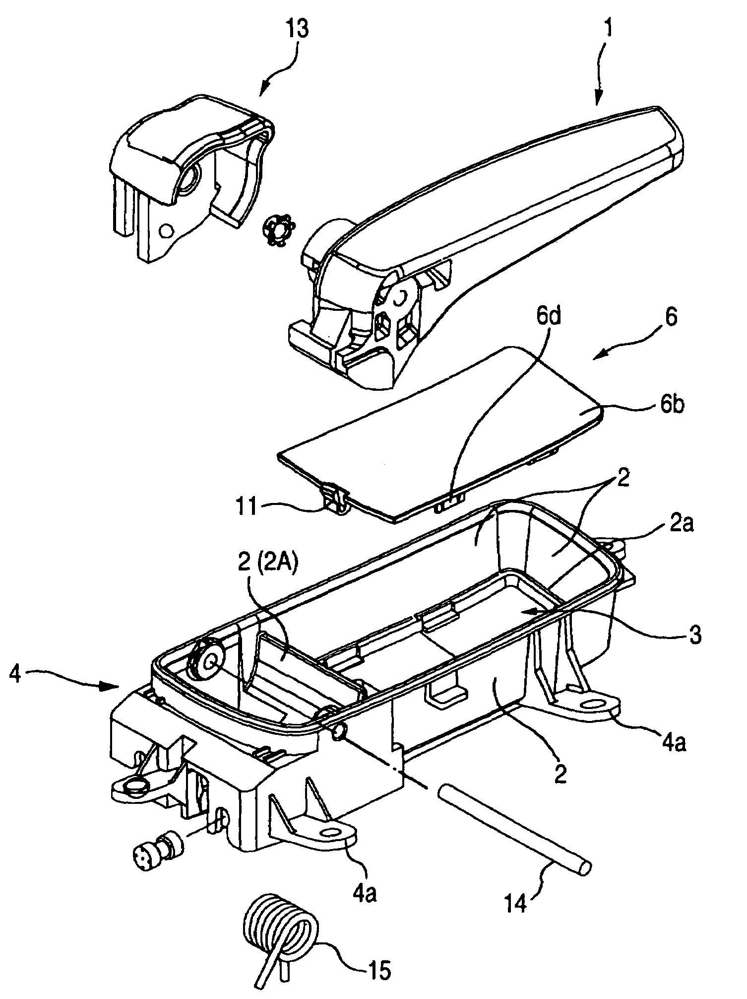
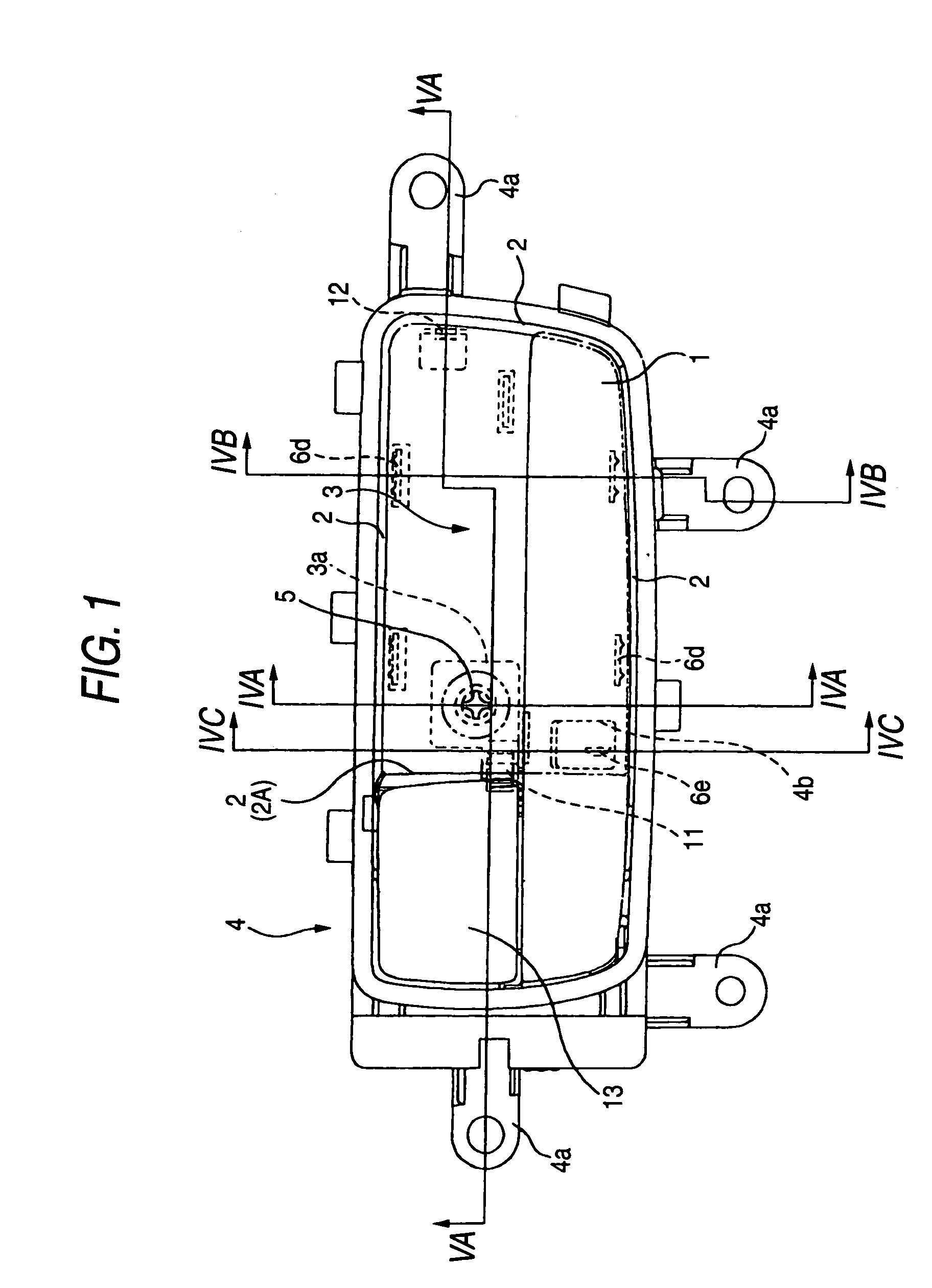
[0009]The present invention has been accomplished while attention is being given to this point. When the fixing portion is covered with the cover body composing the bottom wall of the hand-operating recess portion, it is possible to prevent the generation of a sense of incongruity which is caused by locally attaching caps and others to the fixing portion. At the same time, when the rising walls are provided at the connecting portion of the cover body, the working property of detaching the cover body can be enhanced.
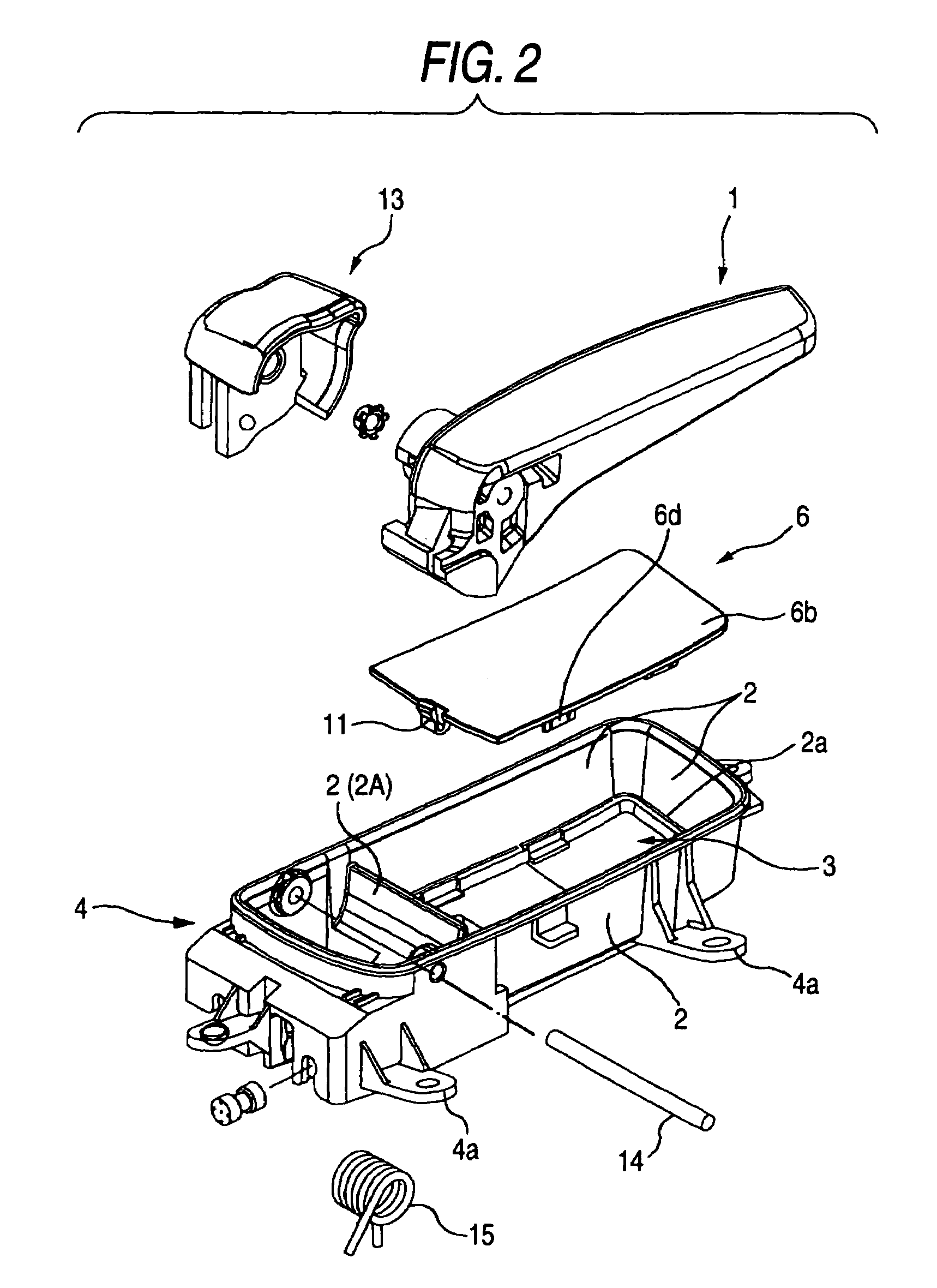
[0011]Since the hooking protrusion is accommodated in the hollow formed on the rising wall, it is difficult for a user to see the hooking protrusion when the handle device is attached to inner panel. Therefore, the beauty of the handle device is seldom spoiled.
[0012]Further, when the second engaging portion is formed in the cover body and arranged at a position opposed to the side edge on which the above engaging leg for release operation is formed and the entire cover body is pushed to the second engaging portion side by the engaging leg for release operation, rattle of the cover body can be prevented.

Problems solved by technology

However, the above conventional example is disadvantageous as follows.
Therefore, the looks of the inside handle device is ugly.
Even in this case in which the above countermeasures have been taken, users may inevitably feel a sense of incongruity in the design of the inside handle device.

Method used


Image

  • Inside door handle device of automobile
  • Inside door handle device of automobile
  • Inside door handle device of automobile

Examples


Embodiment Construction

[0018]As shown in FIGS. 1 and 2, the inside handle device is composed in such a manner that the operation handle 1 and the lock lever 13 are pivotally connected round the shaft 14 in the handle case 4. The operation handle 1 and the lock lever 13 are connected to a lock device (not shown) via a rod and others not shown in the drawing. When the operation handle 1 is turned resisting a reaction force of the spring 15, the door can be opened. When the lock lever 13 is operated, the door opening operation conducted by the operation handle 1 with respect to the lock device is canceled. Therefore, the door can be prevented from being opened while the vehicle is running.

[0019]The handle case 4 is formed into a frame shape. The inside of the frame is divided into a region in which the shaft of the operation handle 1 is accommodated and a residual region by the shielding wall 2A formed at the base end portions of the operation handle 1 and the lock lever 13. This residual region becomes the ...


PUM


Abstract

An inside door handle device of an automobile comprises: a handle case; a cover body for covering a fixing portion of the handle case to a vehicle body; a hollow formed on the rising wall of the hand-operating recess portion; an engaging step portion formed in a bottom wall of the hollow; and an engaging leg for release operation, formed in the cover body.The engaging leg for release operation includes an engaging portion elastically engaged with the engaging step portion; and a hooking protrusion capable of being hooked from above, accommodated in the hollow in the engaging state with the engaging step portion.

Description

BACKGROUND OF THE INVENTION[0001]The present invention relates to an inside door handle device of an automobile.[0002]An inside handle device fixed to an inner panel with clamping pieces is known, for example as disclosed in JP-A-2000-087601. The inside handle device in JP-A-2000-087601 includes: a handle case for pivotally supporting an operation handle and lock lever; and a decorative frame elastically engaged with the handle case. This inside handle device is attached to a vehicle body (inner panel) in such a manner that, first, the handle case is fixed to the inner panel and then the decorative frame is fixed so that the door trim is pinched in the peripheral edge.[0003]However, the above conventional example is disadvantageous as follows. Clamping pieces such as screws used for fixing the decorative frame are exposed outside at the point of time when the work of attaching the inside handle device to the inner panel has been completed. Therefore, the looks of the inside handle d...

Claims


Application Information

Patent Timeline
Patent Type & Authority Patents(United States)
IPC IPC(8): E05B3/00E05B1/00E05B79/06E05B85/12
CPCE05B85/12E05B85/13Y10S292/53Y10T292/82Y10T292/85
Inventor KAKITA, KOUSUKE
Owner ALPHA
Learn More