Mounting structure of electronic device, and pneumatic tire onto which electronic device is mounted by such mounting structure

a technology of mounting structure and electronic device, which is applied in vehicle tyre testing, instruments, roads, etc., can solve the problems of cracks fractures may tend to occur from cracks, and stress is concentrated on the base end of patch straps intensively

Active Publication Date: 2011-01-25
BRIDGESTONE CORP
View PDF24 Cites 23 Cited by
  • Summary
  • Abstract
  • Description
  • Claims
  • Application Information

AI Technical Summary

Benefits of technology

[0007]Then, an object of the present invention is, in order to solve the above-mentioned issues, to provide a novel mounting structure that can restrain an intensive stress concentration by deconcentrating a force applied on the electronic device under a pneumatic tire running, and to provide a pneumatic tire with the novel mounting structure.
[0022]According to this configuration, restrained can be rattling of the electronic device under expansion and contraction of the inner liner in a tire circumferential direction under the pneumatic tire running, so that that the mounting of the electronic device can be made stable.

Problems solved by technology

However, since the electronic device can be attached on the inner liner with being dangled on the patch strap as described above, a stress is concentrated on a base end of the patch strap intensively due to a force applied on the electronic device under a pneumatic tire running.
As a result, a crack may tend to occur on the base end of the patch strap and a fracture may tend to occur from the crack.
Therefore, it is hard to improve durability of the above-described attaching structure.

Method used


Image

  • Mounting structure of electronic device, and pneumatic tire onto which electronic device is mounted by such mounting structure
  • Mounting structure of electronic device, and pneumatic tire onto which electronic device is mounted by such mounting structure
  • Mounting structure of electronic device, and pneumatic tire onto which electronic device is mounted by such mounting structure

Examples


first embodiment

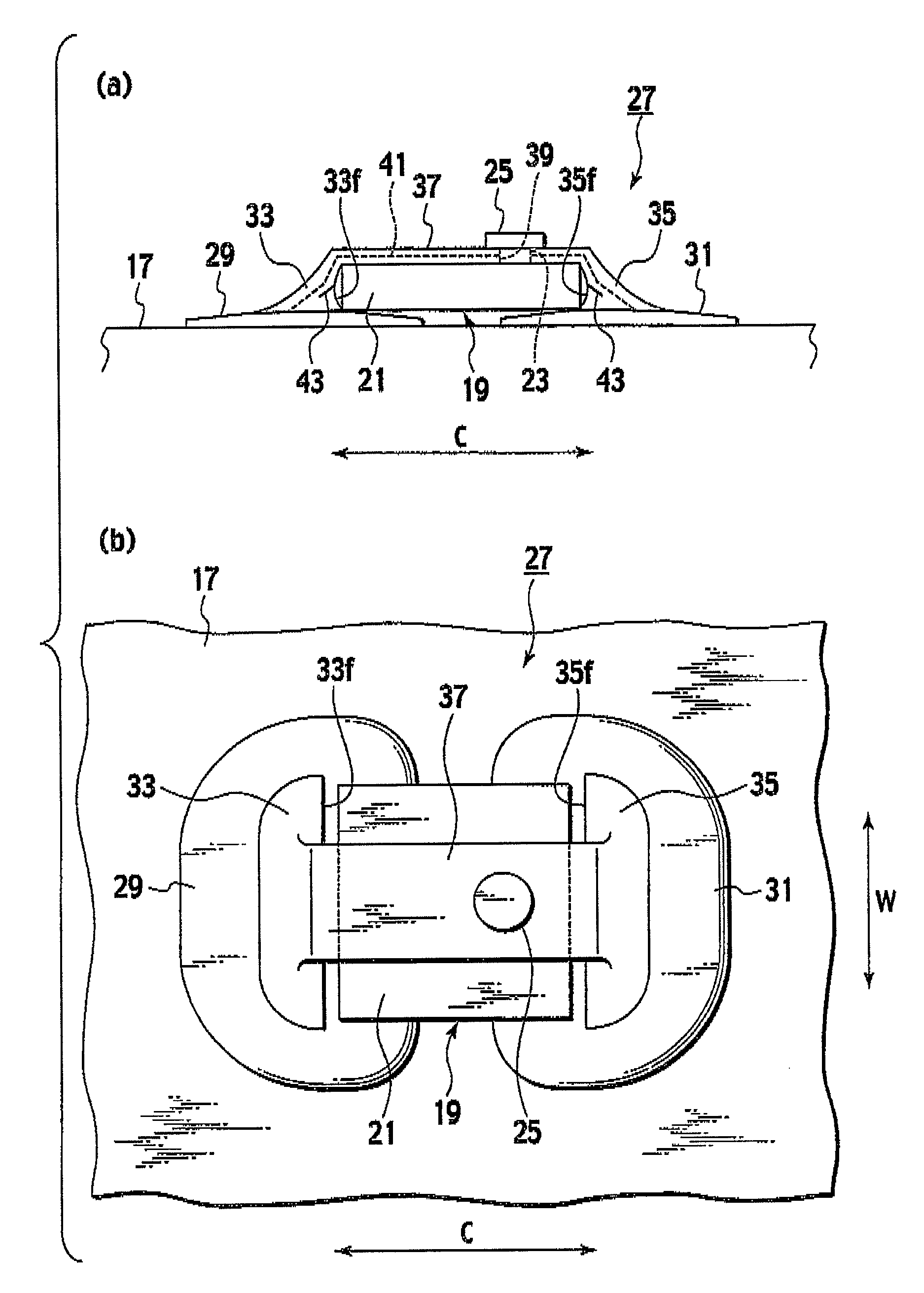
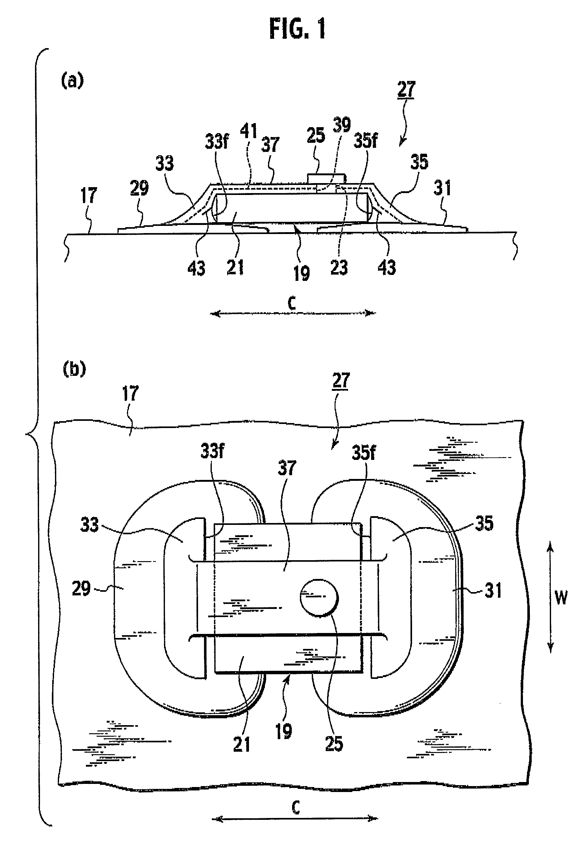
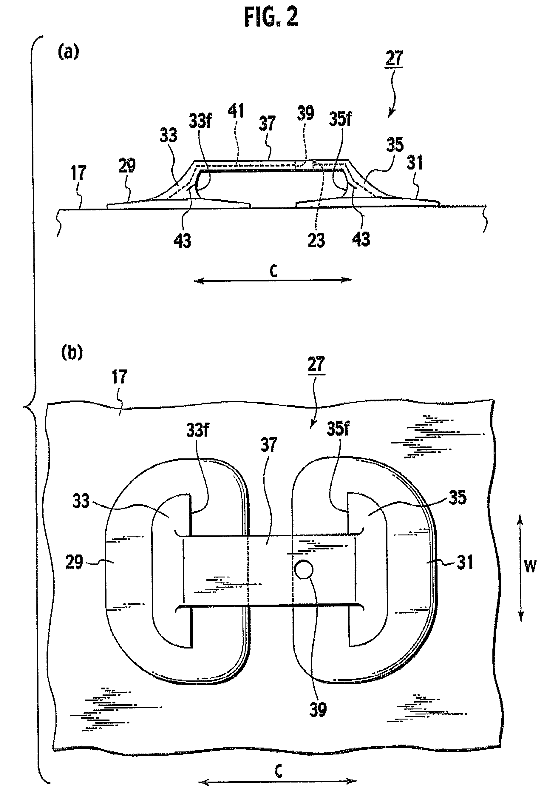
[0040]A first embodiment according to the present invention will be explained with reference to FIGS. 1 to 3.

[0041]As shown in FIG. 3, a pneumatic tire 1 in the first embodiment can be filled with air as working gas and has a pair of annular bead fillers 5 capable of being tightly seated on a rim 3. A bead core 7 is mounted within each of the bead fillers 5. In addition, a carcass 9 is integrally provided between the pair of bead fillers 5 as a structural member. This carcass 9 has a troidal cross-sectional shape. Further, a multiply belt 11 is integrated on an outer circumferential surface of the carcass 9.

[0042]A tread 13 capable of being contacted with a road surface is integrally provided on the outer circumferential surface of the carcass 9 so as to and surround the belt 11. Sidewalls 15 for protecting the carcass 9 are integrally provided on outer side surfaces of the carcass 9. In addition, an inner liner 17 for preventing air permeation is also integrally provided on an inne...


PUM


Abstract

A bonded patch is bonded on a surface of an inner liner. A first patch wall having a first wall surface for restraining a movement of an electronic device main body in one direction is provided integrally with the bonded patch so as to project toward a tire center. A second patch wall having a second wall surface for restraining a movement of an electronic device main body in another direction is provided integrally with the bonded patch so as to project toward the tire center. A connecting segment is provided between the first patch wall and the second patch wall with bridging them for engaging a top of the electronic device main body. A crack occurrence on the mounting structure is prevented by deconcentrating a force applied on an electronic device to overall of the mounting structure to restrain an intensive stress concentration on the mounting structure.

Description

TECHNICAL FIELD[0001]The present inventions relate to a pneumatic tire and a mounting structure for mounting an electronic device (a transponder, an inner pressure monitoring device or the like) on an inner liner of the pneumatic tire.BACKGROUND ART[0002]A Patent Document 1 shows a prior art of an attaching structure for attaching an electronic device such as a transponder on an inner liner of a pneumatic tire. A specific structure according to this prior art of an attaching structure will be explained hereinbelow.[0003]Specifically, a bonded patch is bonded onto a surface of an inner liner. The bonded patch is made of rubber. In addition, a patch strap is integrally formed with the bonded patch. The patch strap is made of rubber. Further, the patch strap can be inserted into a through hole formed in an electronic device main body. An engaged hole is formed on an end of the patch strap, which can be engaged with an engaging pin provided on the electronic device main body.[0004]There...

Claims


Application Information

Patent Timeline
Patent Type & Authority Patents(United States)
IPC IPC(8): G01M17/02
CPCB60C23/0493B29D2030/0072B29D2030/0077
Inventor HIRONAKA, TAKAYOSHI
Owner BRIDGESTONE CORP
Why Eureka
Try Eureka