System and method for high z material detection

a detection system and material technology, applied in the field of high-z material detection system and method, can solve the problems of inability to equip each one with its own photomultiplier, current nuclear material detection technology is limited to x-ray and gamma ray equipment, etc., to improve the signal-to-noise ratio, and improve the detection signal-to-noise ratio

Inactive Publication Date: 2009-09-10
CELIGHT
View PDF5 Cites 13 Cited by
  • Summary
  • Abstract
  • Description
  • Claims
  • Application Information

AI Technical Summary

Benefits of technology

[0017]The muon velocity measurement unit may operate separately from the muon deflection measurement. Alternatively, the velocity measurement unit may be combined with the coordinate and incidence angle measurement unit. In the preferred embodiment the muon velocity measurement unit is positioned below the coordinate and angle measurement detectors. In one embodiment a threshold Cerenkov counter is implemented for rejection of the contribution of muons with energies above some predetermined threshold to improve the signal-to noise rati

Problems solved by technology

The small size of each independent scintillator means that many readout channels (typically tens of thousands) are required, and it is not practic

Method used


Image

  • System and method for high z material detection
  • System and method for high z material detection
  • System and method for high z material detection

Examples


Embodiment Construction

[0028]The present invention now will be described more fully hereinafter with reference to the accompanying drawings, in which the preferred embodiments of the invention are shown. This invention may, however, be embodied in many different forms and should not be construed as limited to the embodiments set forth herein; rather, these embodiments are provided so that this disclosure will be thorough and complete, and will fully convey the scope of the invention to those skilled in the art.

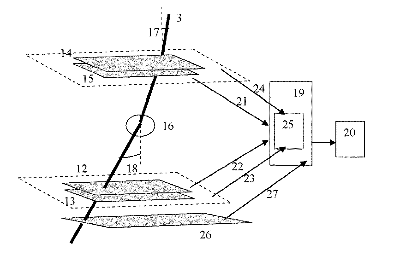
[0029]In one embodiment of the present invention, the muon detectors are the wire detectors similar to described above with the gratings make an anode, one above and one below the wires, while the wires make an anode. The gratings are printed strips, not wires, and the anode wires are spaced closer than the strips. The combination of a very thin (typically 50 microns) wire yielding a very high electrostatic field near the wire, very dense spacing of wires (typically 1.5 mm), critical choice of the g...


PUM


Abstract

A method and system for high Z material revealing using muon detection technique is presented. The system measures muons' coordinates, velocities, incidence angles and leaving angles. Two series of detectors: one above and one below the interrogated volume are used. A muon trajectory deviation from an expected trajectory is used for the decision making on the presence of high Z material inside the volume. The muon velocity is measured using either a ring Cerenkov counter, a transition radiation detector or/and a threshold Cerenkov counter. The expected trajectory is calculated basing on known particle velocity.

Description

CROSS-REFERENCE TO RELATED APPLICATIONS[0001]The present invention claims the benefit of U.S. Provisional Application Ser. No. 61 / 013,791, filed Dec. 14, 2007; the present invention is a continuation-in-part of U.S. patent application Ser. Nos. 11 / 626,920, filed Jan. 25, 2007 and 11 / 947,058, filed Nov. 29, 2007, all of which are fully incorporated herein by reference.FIELD OF INVENTION[0002]This invention relates generally to the systems and methods for revealing hidden uranium, plutonium and other high Z materials using muon detection technique.BACKGROUND OF THE INVENTION[0003]A flow of cosmic rays constantly bombards Earth. Primary cosmic rays consist of single protons (about 90% of all cosmic rays) and alpha particles (majority of the remaining 10%). When these primary cosmic rays hit Earth's atmosphere at around 20,000 m above the surface, the impacts cause nuclear reactions, which produce pions. These pions decay into a muon and muon neutrino at about 9000 m altitude. Many muon...

Claims


Application Information

Patent Timeline
IPC IPC(8): G01F23/00
CPCG01T1/2935
Inventor GOLDBERG, JACQUESSHPANTZER, ISAACACHIAM, YASKOVREINGAND, NADEJDA
Owner CELIGHT
Why Eureka
Try Eureka