Ball mark and method of using the same

a ball mark and ball technology, applied in the field of golf, can solve the problems of difficult identification on the green, difficult to locate smaller marks, etc., and achieve the effect of improving the method of using the same, improving the game of golf, and improving the accuracy of ball marks

Inactive Publication Date: 2009-10-01
MURKEN JOSEPH S +1
View PDF10 Cites 1 Cited by
  • Summary
  • Abstract
  • Description
  • Claims
  • Application Information

AI Technical Summary

Benefits of technology

[0005]It is an object to improve ball marks.
[0006]It is another object to improve the game of golf.
[0007]It is a further object to improve the method of using a ball mark.
[0008]Accordingly, the present invention in one embodiment is directed to a ball mark which includes a first portion and a second portion, wherein the second portion is movably associated with the first portion and capable of being moved in and out of a generally common plane with the first portion. When in a common plane and placed on a putting surface, a golf ball can roll over the ball mark without substantially affecting a path of the golf ball. When the second portion is generally out of plane with first portion and the first portion is disposed on the putting surface, the second portion extends above the first portion to more readily enable a player to view the ball mark on the putting surface for purposes of aligning one's putt and to aid in avoiding walking in one's line to the hole. In a preferred embodiment, at least a surface of the second portion can be provided with a contrasting colored surface to that of the putting surface to aid visibility thereof.
[0009]Another aspect of the invention is that the invention provides for easy finding and storage of the ball mark. The ball mark is equipped with means for retaining the first and second portions in generally parallel and non parallel positions with respect to one another. In the case of non parallel positions, the second portion can be pivoted, for example, from a generally co-planar position to an angled position and to a generally parallel position with respect to the first portion. Co-planar and non-planar positions provide utility in use on the putting surface. The generally parallel positions can be used to clip to an article of clothing, for example, to aid in its easy location for use. A method of using the ball mark is also provided.

Problems solved by technology

A common problem with markers is that they can be hard to identify on a green, depending on the mark's color and the time of year, i.e., the change in color with the season.
One problem with the plastic marks is that they often break.
Another problem facing a ball mark is that a smaller mark is often hard to locate in one's pocket as well as on the green but is preferred for marking on the green to pose less of an obstruction to another player's line of play.

Method used


Image

  • Ball mark and method of using the same
  • Ball mark and method of using the same
  • Ball mark and method of using the same

Examples


Embodiment Construction

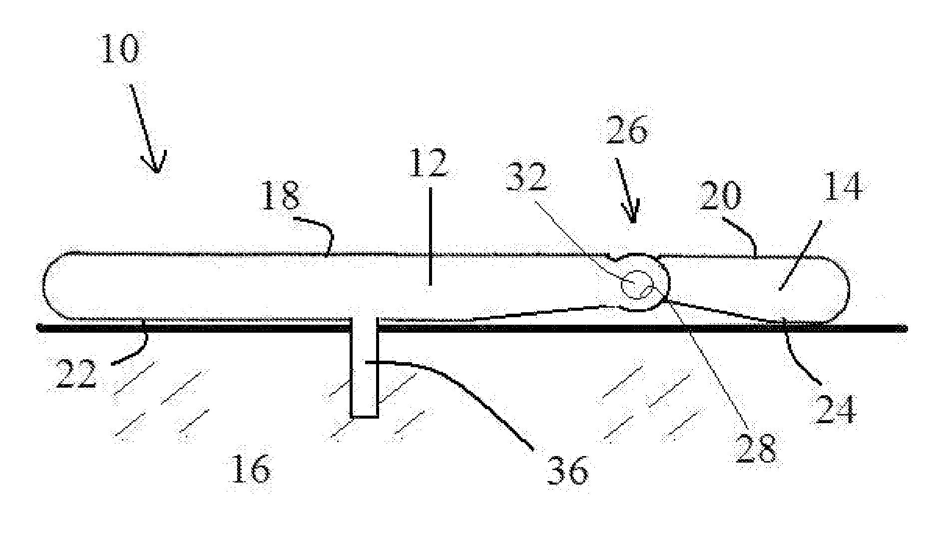
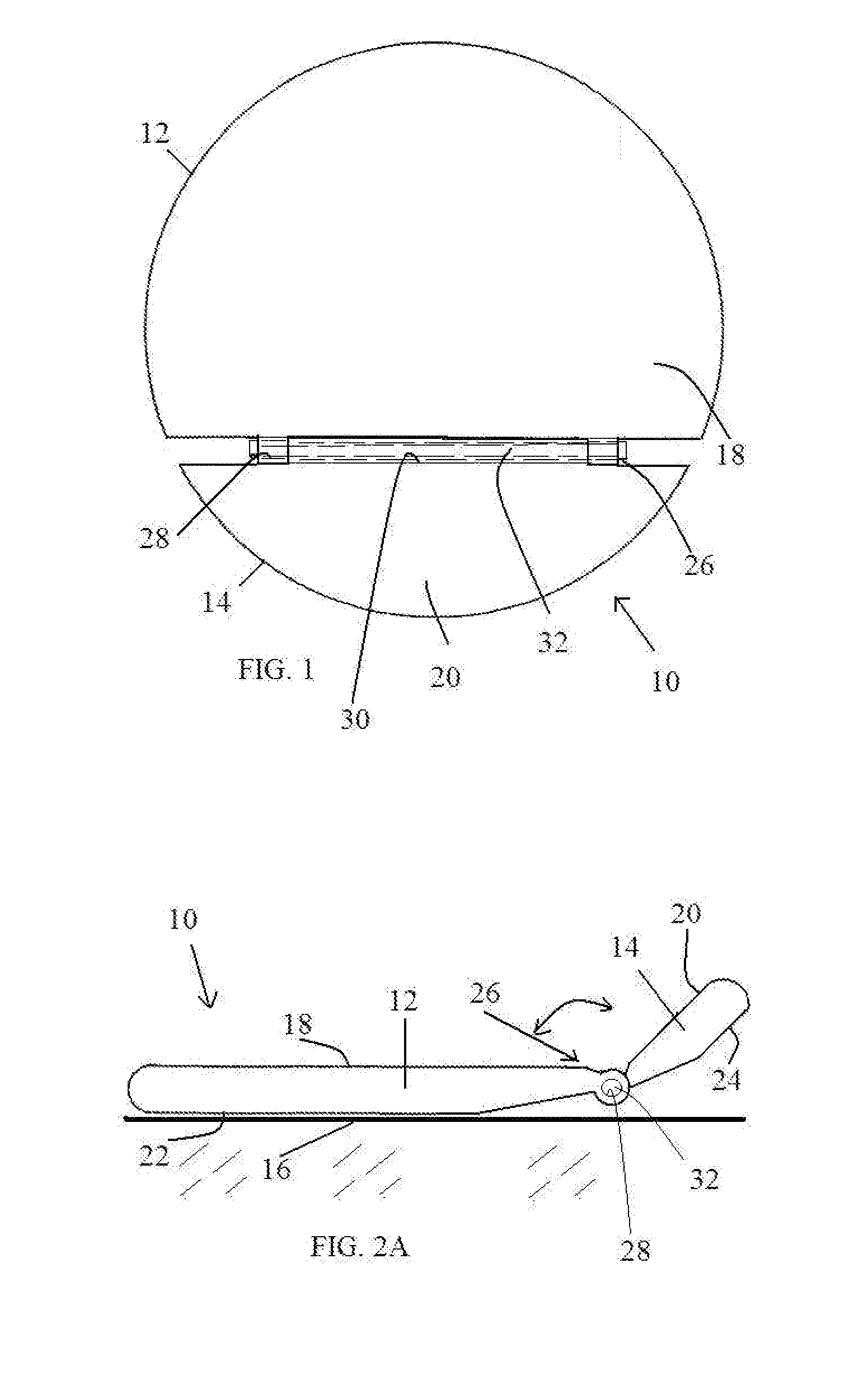
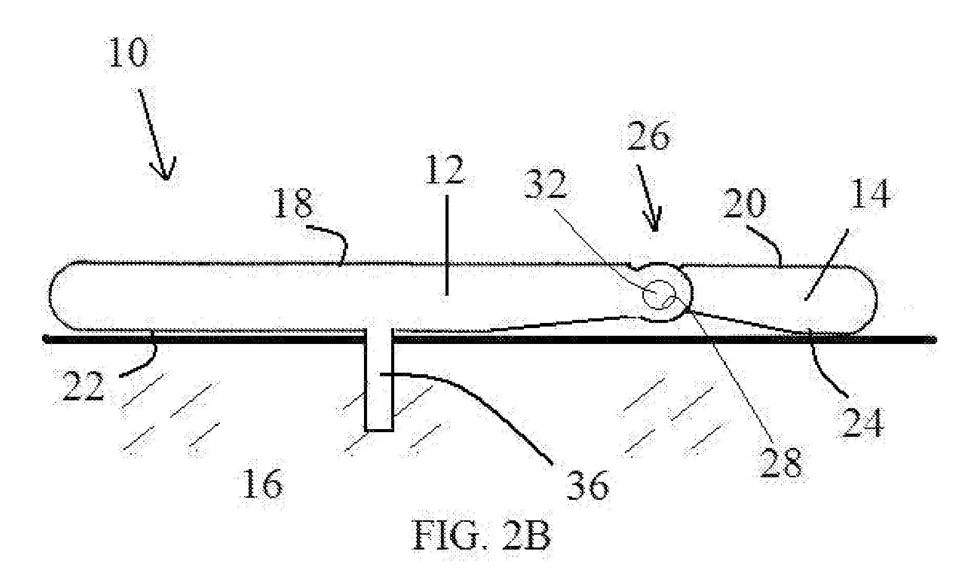
[0014]Referring now to the present invention, a ball mark according to the present invention is generally designated by the numeral 10. Here, the ball mark 10 is shown to be generally disc shaped. It is contemplated that other shapes can be employed to carry out the invention and are contemplated within the instant invention and therefore the description with respect to such shapes are exemplary.

[0015]The ball mark 10 includes a first portion 12 and a second portion 14. The first portion 12 can include a larger part of the ball mark 12 and hence larger part of the disc shape in contrast to the second portion 14 for purposes of demonstrating a working embodiment of the invention. The second portion 14 can be movably associated to the first portion 12 and capable of being moved in and out of a generally common plane (or parallel position) with the first portion 12.

[0016]When sharing a common plane as seen in FIGS. 1 and 2B and placed on a putting surface 16, the mark 10 permits a golf...


PUM


Abstract

A ball mark includes a first portion and a second portion, wherein the second portion is generally non planar with respect to the first portion and when the first portion is disposed on a putting surface, the second portion extends above the first portion to more readily enable a player to view the ball mark on the putting surface for purposes of aligning one's putt and to aid in avoiding walking in one's line to a hole. The first portion and the second portion are movably associated with each other and can move in and out of a generally common plane.

Description

FIELD OF INVENTION[0001]The present invention relates to golf. More particularly, the present invention relates to a ball mark and method of using the same.RELATED ART[0002]Under The Rules of Golf, there is no specification that the object used to mark the position of a ball must be of a certain size or shape. Rather, it is recommended (in the Note to Rule 20-1 of The Rules of Golf) that a player use a small coin or other similar object. However, it is also permissible to use other objects such as a tee, divot repair tool, toe of a club, etc. Traditionally, marks have included the likes of coins or disc like members which are made of metals and plastics. The more recent improvements in the ball mark have been to include an outwardly extending pin from one side of the mark for use in penetrating the ground and aiding in retaining the same in the ground.[0003]A common problem with markers is that they can be hard to identify on a green, depending on the mark's color and the time of ye...

Claims


Application Information

Patent Timeline
Patent Type & Authority Applications(United States)
IPC IPC(8): A63B57/00
CPCA63B55/008A63B2210/50A63B57/0075A63B57/353A63B55/408A63B57/207
Inventor MURKEN, JOSEPH S.GRAHAM, R. WILLIAM
Owner MURKEN JOSEPH S
Why Eureka
Try Eureka