Motorized window shade system and mount

a motorized and window shade technology, applied in the direction of door/window protective devices, curtain suspension devices, wing accessories, etc., can solve the problems of reducing the accuracy of the effect of the motorized window shade, and reducing the size of the gap

Inactive Publication Date: 2009-12-17
KATES LAWRENCE
View PDF99 Cites 119 Cited by
  • Summary
  • Abstract
  • Description
  • Claims
  • Application Information

AI Technical Summary

Benefits of technology

[0011]The system and method disclosed herein solves these and other problems by providing a remotely-controllable, self-powered, user-installable motorized window shade. In one embodiment, a mounting system allows the window shade material to be placed relatively close to the edge of the window casing, thus reducing the size of the gap between the window shade and the window casing. In one embodiment, the motorized roll-up window shade includes a controller, a tubular motor provid

Problems solved by technology

If the user lets go of the shade as the shade is traveling upward the spring in the shade will cause the shade to travel upward out of control.
The setting of multiple shades at the same relative position can be a very time consuming process.
The manually-operated shades are not capable of receiving inputs from time clocks, photo sensors, occupant sensors or infrared hand held transmitters.
Installation of such wiring is beyond the capabilities of most homeowners, and thus, such units must be installed by a professional installer.
The prior art devices generally suffer from a number

Method used


Image

  • Motorized window shade system and mount
  • Motorized window shade system and mount
  • Motorized window shade system and mount

Examples


Embodiment Construction

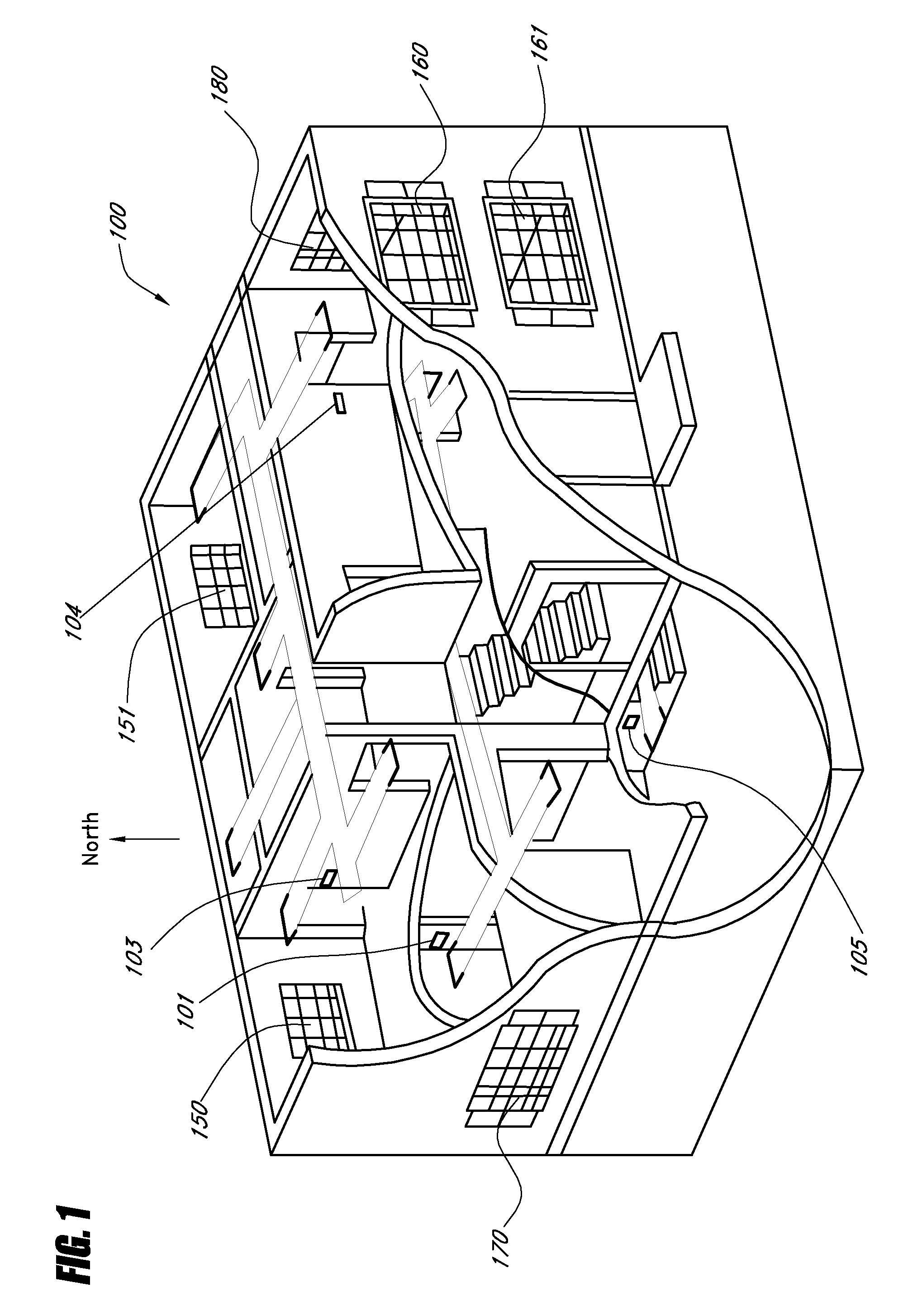
[0055]FIG. 1 shows a home 100 with ducts for heating and cooling and windows on various sides of the house. For example, the home 100 includes north-facing windows 150, 151, an east-facing window 180, south-facing windows 160, 161, and a west-facing window 170. In the home 100, an HVAC system provides heating and cooling light to the system of windows. In a conventional system, a thermostat monitors the air temperature and turns the HVAC system on or off. In a zoned system, sensors 101-105 monitor the temperature in various areas (zones) of the house. A zone can be a room, a floor, a group of rooms, etc. The sensors 101-105 detect where and when heating or cooling is needed. Information from the sensors 101-105 is used to control motors that adjust the flow of air to the various zones. The zoned system adapts to changing conditions in one area without affecting other areas. For example, many two-story houses are zoned by floor. Because heat rises, the second floor usually requires m...


PUM


Abstract

An electronically-controlled roll-up window shade that can easily be installed by a homeowner or general handyman is disclosed. The motorized shade includes an internal power source, a motor, and a communication system to allow for remote control of the motorized shade. One or more motorized shades can be controlled singly or as a group. In one embodiment, the motorized shades are used in connection with a zoned or non-zoned HVAC system to reduce energy usage. In one embodiment, the motorized shade is configured to have a size and form-factor that conforms to a standard manually-controlled motorized shade. In one embodiment, a group controller is configured to provide thermostat information to the motorized shade. In one embodiment, the group controller communicates with a central monitoring system that coordinates operation of one or more motorized shades. In one embodiment, the internal power source of the motorized shade is recharged by a solar cell.

Description

BACKGROUND[0001]1. Field of the Invention[0002]The present invention relates to motorized window shades.[0003]2. Description of the Related Art[0004]A roll-up window shade is well known. The shade can be moved manually up or down in front of a window to control the light level, room temperature, light flow, or to provide privacy. The known roll-up shade is relatively inexpensive and is easy to install. If the shade is damaged, a new shade can be replaced easily. These types of shades are sold in retail stores and do-it-yourself centers across the U.S. The shades are typically stocked in 3, 4, 5 and 6 foot widths. The shade can easily be cut to the proper width with a cutting device either at the point of sale or at installation time. The installer or homeowner can measure and install the shade on the same site visit.[0005]The conventional roll-up shade has a first pin end and a second spring end with a rectangular barb extending outwardly. The pin end is inserted into a circular hol...

Claims


Application Information

Patent Timeline
IPC IPC(8): E06B9/68E05F15/20
CPCE05Y2400/40E05Y2400/42E05Y2800/21E05F15/71E06B9/50E06B9/72E06B2009/6818E06B9/44E05Y2900/106E05Y2900/00
Inventor KATES, LAWRENCE
Owner KATES LAWRENCE
Why Eureka
Try Eureka