Electronic device with chip card

a chip and electronic device technology, applied in the direction of electrical apparatus casings/cabinets/drawers, instruments, printed circuit non-printed electric components association, etc., can solve the problem of difficulty for users to grasp

Active Publication Date: 2010-01-21
SHENZHEN FUTAIHONG PRECISION IND CO LTD +1
View PDF1 Cites 2 Cited by
  • Summary
  • Abstract
  • Description
  • Claims
  • Application Information

AI Technical Summary

Problems solved by technology

However, the exposed part of the chip card is usually small and therefore

Method used


Image

  • Electronic device with chip card
  • Electronic device with chip card
  • Electronic device with chip card

Examples


Embodiment Construction

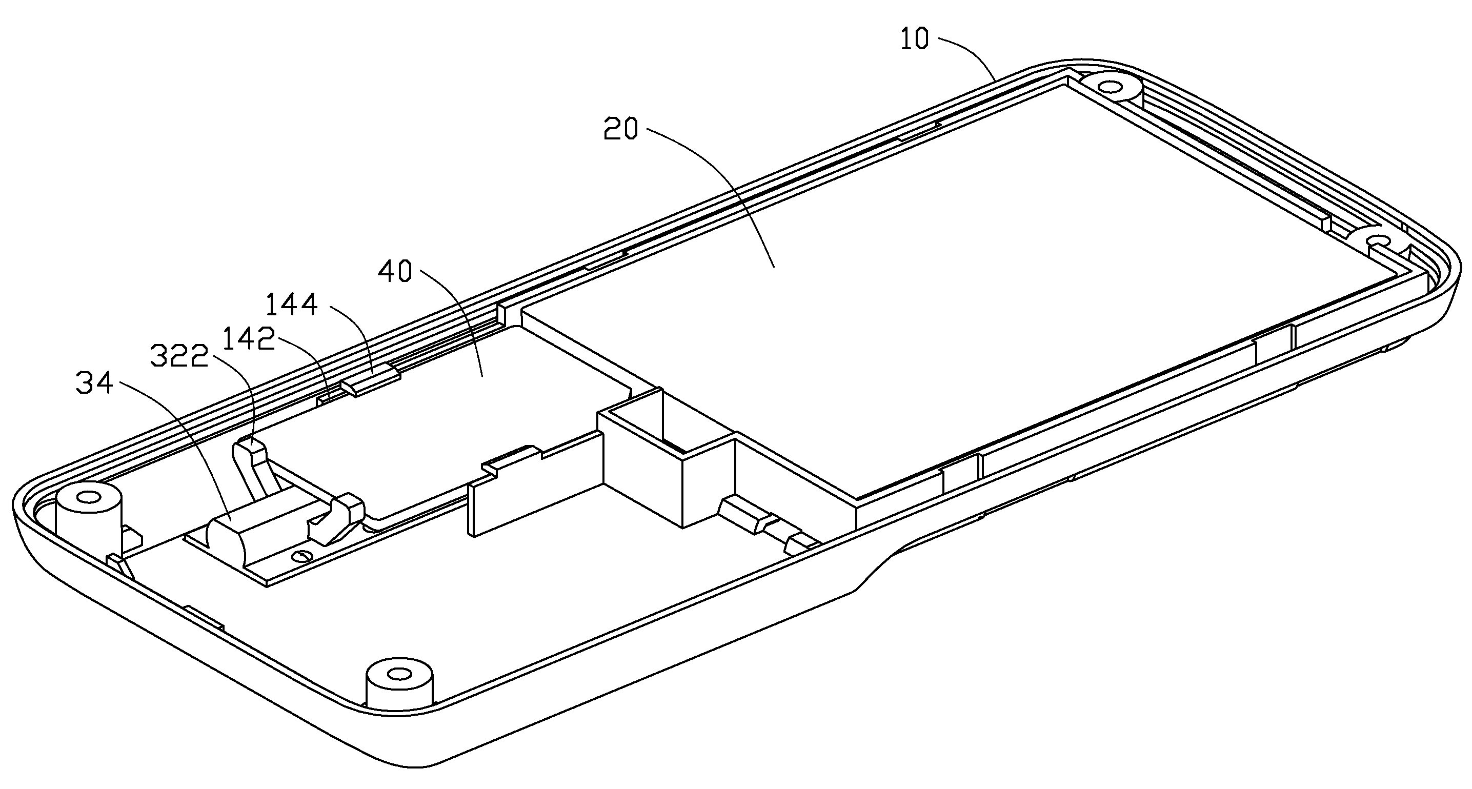
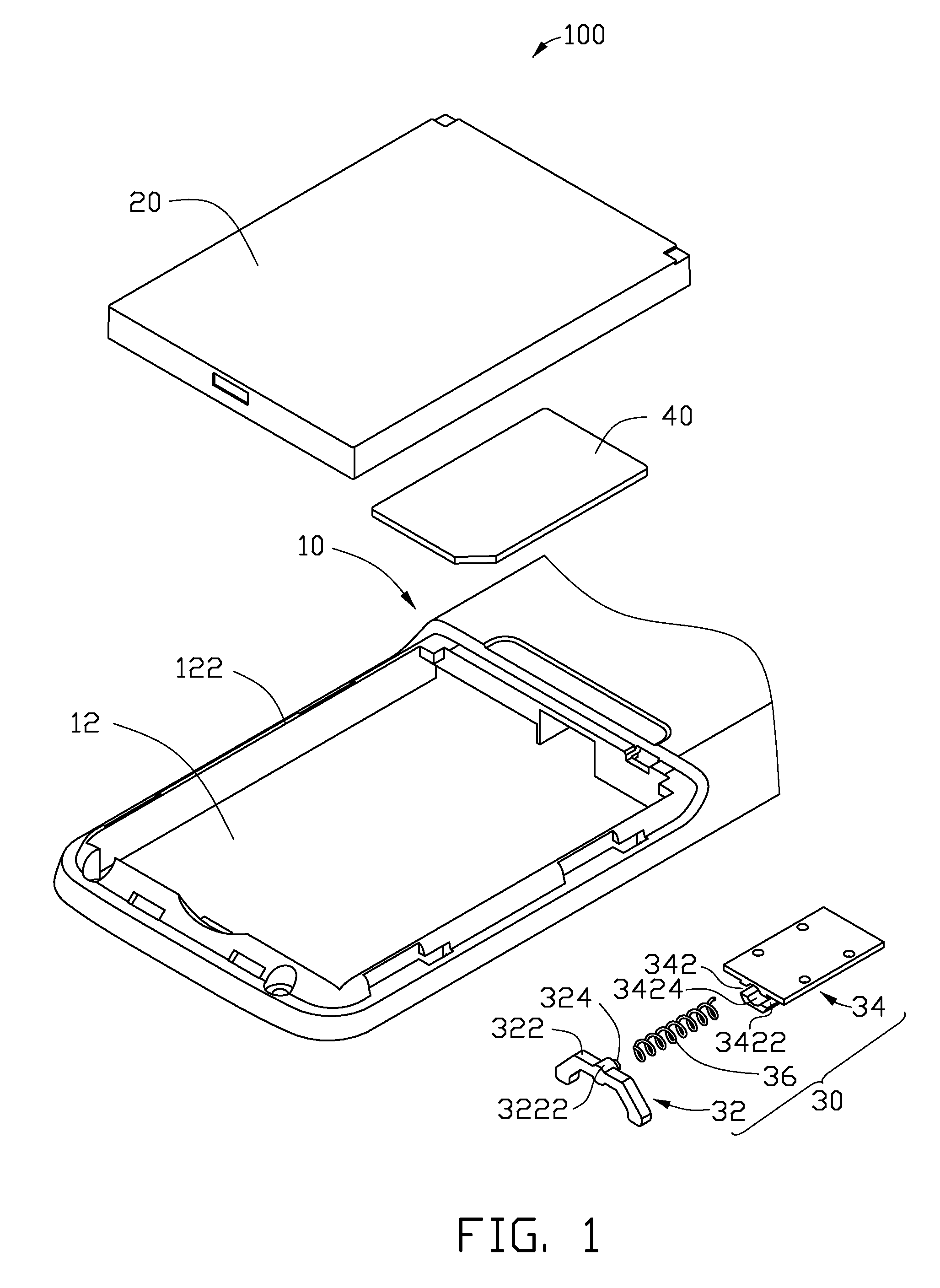
[0013]FIG. 1 shows an exemplary electronic device 100 (such as a mobile phone) including a housing 10, a battery 20 configured to be received within the housing 10, and an ejecting mechanism 30 configured to be mounted in the housing 10. Referring to FIG. 5, a chip card 40 (e.g., SIM card) is secured by the battery 20 and the ejecting mechanism 30.

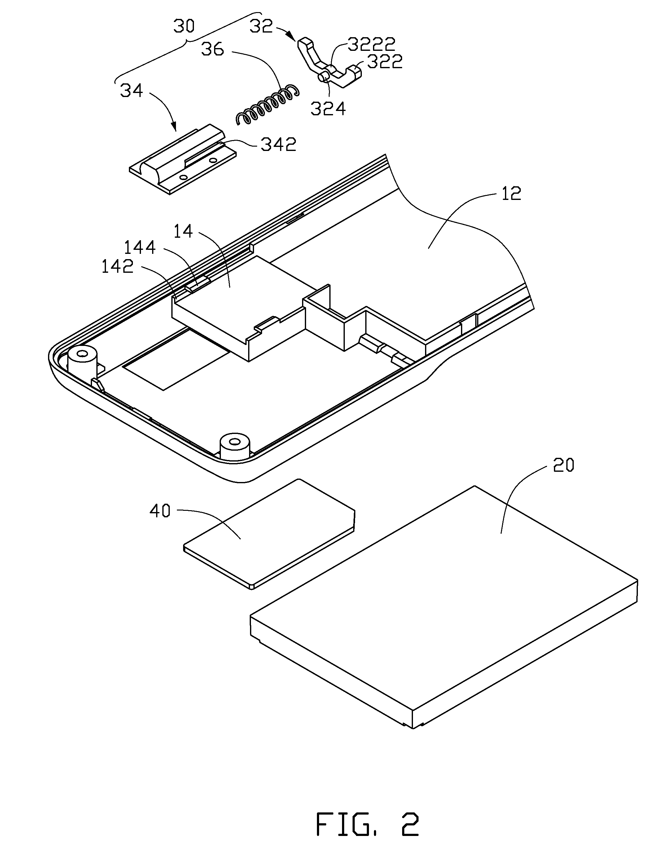
[0014]Referring to FIG. 2, the housing 10 defines a chamber 12 at one end for accommodating the battery 20. A peripheral wall 122 surrounds the chamber 12. A base 14 is formed on the housing 10 adjacent to the chamber 12, and the base 14 is configured for supporting and securing the chip card 40. The base 14 has two opposite edges, and each edge has an upwardly protruding stopping section 142. Each stopping section 142 has a hook 144 extending horizontally from a distal end of the stopping section 142 and above the base 14 towards the center thereof.

[0015]Referring to FIGS. 1 and 3, the ejecting mechanism 30 includes a sliding member 32, a...


PUM


Abstract

A electronic device (100) includes a removable chip card (40) for carrying information, comprise a housing (10) and a ejecting mechanism (30). The housing (10) defines a chamber (12) and a base (14) formed adjacent to the chamber. The chamber (12) is used for accommodating a battery (20) therein. The base (14) is used for receiving the chip card (40) therewith. The ejecting mechanism (30) is mounted in the housing (10) and includes a sliding member (32) and an elastic member (36). When the battery (20) is accommodated in the chamber (12), the chip card (40) is secured between the sliding member (32) and the battery (20). When the battery (20) is removed from the chamber (12), the elastic member (36) biases the sliding member (32) to eject the chip card (40) outwardly from the base (14).

Description

BACKGROUND[0001]1. Field of the Invention[0002]The present invention relates to electronic devices having chip cards, and particularly to an electronic device having a mechanism for ejecting a chip card.[0003]2. Description of Related Art[0004]Commonly, portable electronic devices such as mobile phones use chip cards retained by a holder.[0005]Typically, chip card holders define a receiving groove for receiving the chip card. The chip card is partly received in the receiving groove to electronically connect to a circuit of the device employing the chip card, and partly exposed so that it may be gripped for removal. However, the exposed part of the chip card is usually small and therefore difficult for a user to grasp in removing the chip card from the holder.[0006]Therefore, there is room for improvement within the art.BRIEF DESCRIPTION OF THE DRAWINGS[0007]Many aspects of the exemplary electronic device with chip card ejecting mechanism can be better understood with reference to th...

Claims


Application Information

Patent Timeline
IPC IPC(8): H05K7/14
CPCG06K13/0806G06K13/08
Inventor QIN, ZHONG-SHUTU, HSIAO-HUASONG, WEN-WEIWANG, JUNLIU, YEZHANG, XU-RI
Owner SHENZHEN FUTAIHONG PRECISION IND CO LTD
Why Eureka
Try Eureka