Separation holding member, cartridge unit, and packaging body

a technology of holding member and holding member, which is applied in the direction of optics, instruments, electrographic processes, etc., can solve the problems of small gap between the cartridge and the separation holding member may become more difficult to grasp and remove, so as to reduce the size of the apparatus, the effect of reducing the size of the separation holding member and reducing the size of the separation

Active Publication Date: 2019-07-25
CANON KK
View PDF1 Cites 2 Cited by
  • Summary
  • Abstract
  • Description
  • Claims
  • Application Information

AI Technical Summary

Benefits of technology

[0003]Although separation holding members such as that described above are removed when using an image forming apparatus and are not a component provided in the image forming apparatus during use, due to demands for reduced apparatus size, further downsizing of separation holding members is required in a similar manner to other components of the image forming apparatus. The separation holding member is provided in a gap between a cartridge and an apparatus main body in order to protect an image bearing member, process means, and a storage element from damage due to impact applied during transportation and delivery when the cartridge is packaged and shipped in a state of being mounted inside the apparatus main body. Progress in downsizing of the apparatus main body results in a smaller gap between the cartridge and the apparatus main body. In order to arrange the separation holding member in such a small gap, a configuration in which the separation holding member is arranged so as to follow a shape of the cartridge is conceivable. However, when arranging the separation holding member so as to follow a shape of the cartridge, there is a concern that the separation holding member may become more difficult to grasp and remove when a user attempts to detach the separation holding member after arrival of the apparatus main body.

Problems solved by technology

Progress in downsizing of the apparatus main body results in a smaller gap between the cartridge and the apparatus main body.
However, when arranging the separation holding member so as to follow a shape of the cartridge, there is a concern that the separation holding member may become more difficult to grasp and remove when a user attempts to detach the separation holding member after arrival of the apparatus main body.

Method used


Image

  • Separation holding member, cartridge unit, and packaging body
  • Separation holding member, cartridge unit, and packaging body
  • Separation holding member, cartridge unit, and packaging body

Examples


embodiment

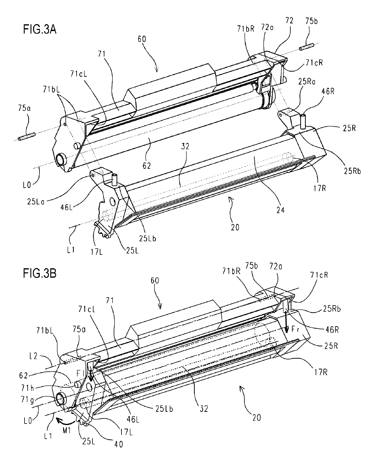
[0049]A separation holding member, a cartridge, an image forming apparatus, and a packaging body according to an embodiment of the present invention will now be described.

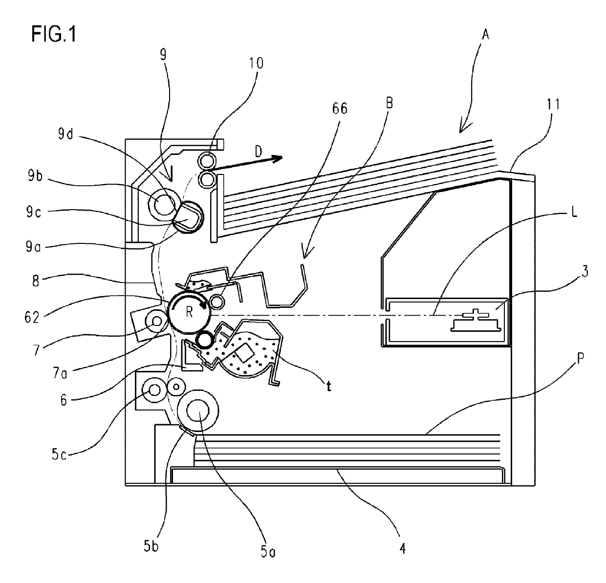
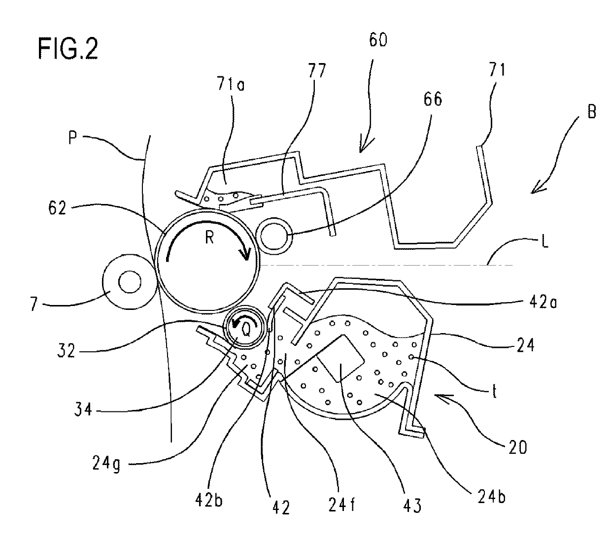
[0050]In this case, a cartridge has at least one of a developer, an image bearing member, and process means that acts on the image bearing member, and the cartridge is attachable to and detachable from an image forming apparatus main body (hereinafter, referred to as an “apparatus main body”). A representative example of a cartridge is a process cartridge. A process cartridge refers to a cartridge which integrates an image bearing member and process means that acts on the image bearing member and which is detachably mounted to an apparatus main body.

[0051]In addition, an image forming apparatus refers to an apparatus that forms an image on a recording material (a recording medium) using an electrophotographic image forming system. Examples of an image forming apparatus include an electrophotographic copier, an elec...


PUM


Abstract

The separation holding member 36 includes a grip portion 36h for detaching the separation holding member 36 from the cartridge B, the grip portion 36h being configured so as to assume a first shape of protruding in a direction of separation from a surface of the cartridge B when the cartridge B mounted with the separation holding member 36 is detached from the apparatus main body A and to assume a second shape in which a gap with the surface of the cartridge B is smaller than in the first shape when the cartridge B mounted with the separation holding member 36 is mounted to the apparatus main body A.

Description

BACKGROUND OF THE INVENTIONField of the Invention[0001]The present invention relates to a separation holding member used in a cartridge of an electrophotographic image forming apparatus.Description of the Related Art[0002]As systems for transferring a developer from a developer bearing member to an image bearing member (developing a latent image) in process means of an electrophotographic image forming apparatus (hereinafter, an image forming apparatus) such as a copier or a printer, a contact developing system and a non-contact developing system are known. In the contact developing system, developing is performed by bringing the image bearing member and the developer bearing member in contact with each other. In the non-contact developing system, developing is performed while holding a minute clearance between the image bearing member and the developer bearing member. Cartridge-system image forming apparatuses are known in which the process means is integrated as a cartridge that i...

Claims


Application Information

Patent Timeline
Patent Type & Authority Applications(United States)
IPC IPC(8): G03G21/18G03G21/16
CPCG03G21/1825G03G21/1647G03G2221/1861G03G21/1814G03G21/1842
Inventor KOGUCHI, KOHEIIIZUKA, YOICHIRO
Owner CANON KK
Why Eureka
Try Eureka