Manufacturing method for a multi-channel copper tube, and manufacturing apparatus for the tube

a manufacturing method and multi-channel technology, applied in the field of manufacturing of copper tubes, can solve problems such as difficulties, and achieve the effect of reducing the friction between the punches and reducing the wear of the punches

Active Publication Date: 2010-01-28
MITSUBISHI MATERIALS CORP
View PDF13 Cites 0 Cited by
  • Summary
  • Abstract
  • Description
  • Claims
  • Application Information

AI Technical Summary

Benefits of technology

[0021]In the manufacturing apparatus for a multi-channel tube of the present invention, the spacing between each of the punches may decrease towards the tips or free ends thereof. In particular, punches spaced outwardly from a central punch may be inclined inwardly towards the central punch towards their free ends or tips thereof. The punches which are furthest from the central punch will be the most steeply inclined. This arrangement will reduce the friction between the punches and the solidified copper thereby reducing wear on the punches.

Problems solved by technology

However, difficulties are encountered when attempting to manufacture multi-channel tube from copper.

Method used


Image

  • Manufacturing method for a multi-channel copper tube, and manufacturing apparatus for the tube
  • Manufacturing method for a multi-channel copper tube, and manufacturing apparatus for the tube
  • Manufacturing method for a multi-channel copper tube, and manufacturing apparatus for the tube

Examples


Embodiment Construction

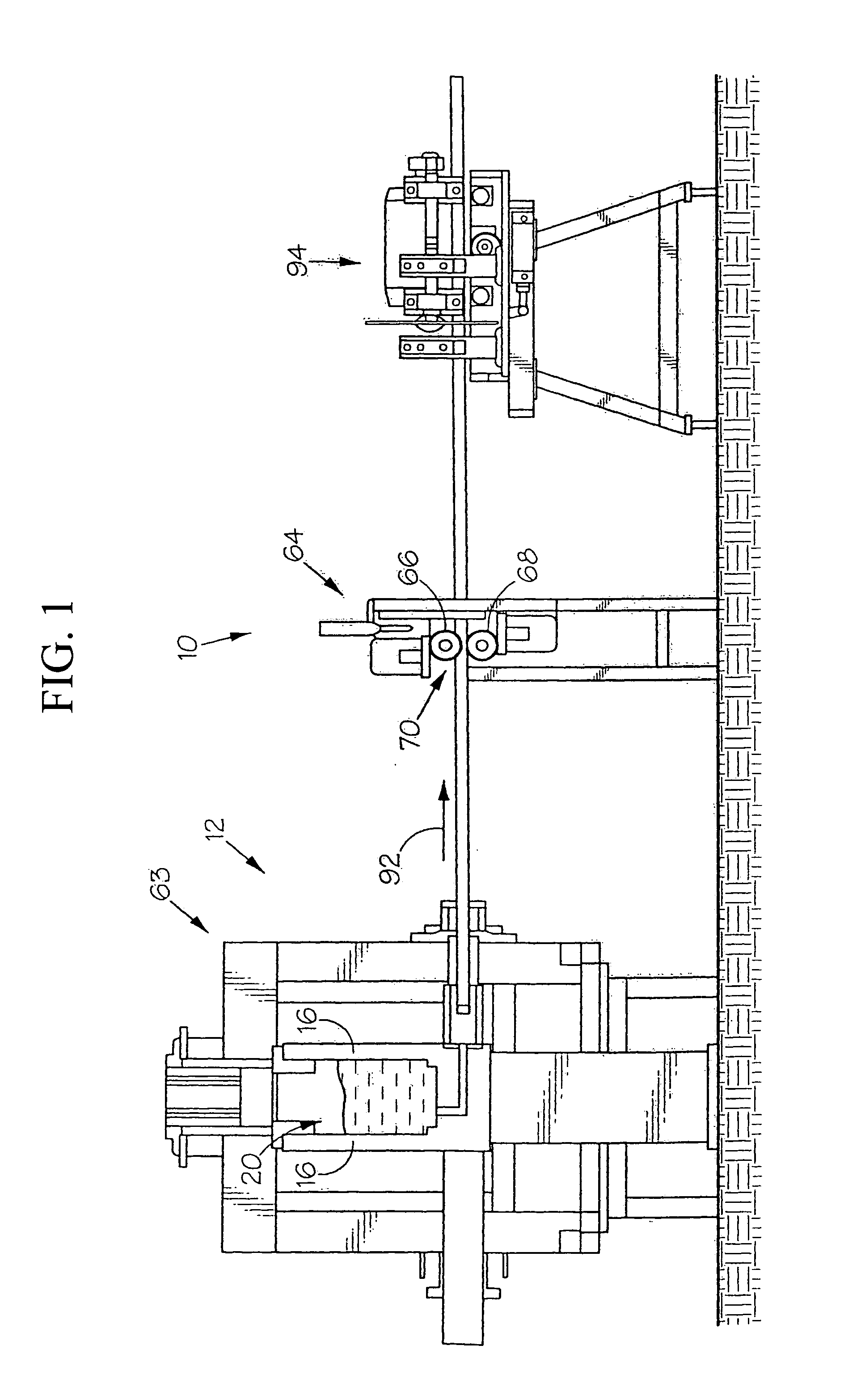
[0057]In FIG. 1 of the drawings, reference numeral 10 refers generally to apparatus for use in the manufacture of multi-channel copper tube 100 in accordance with the invention.

[0058]The multi-channel copper tube 100 is composed of a plurality of integrally formed tubes 101 being arranged in a line (refer to FIG. 11). In each of the tubes 101, a channel 102 is formed.

[0059]The apparatus 10 includes a casting unit, generally indicated by reference numeral 12 and tube drawing apparatus, generally indicated by reference numeral 14 (FIG. 10).

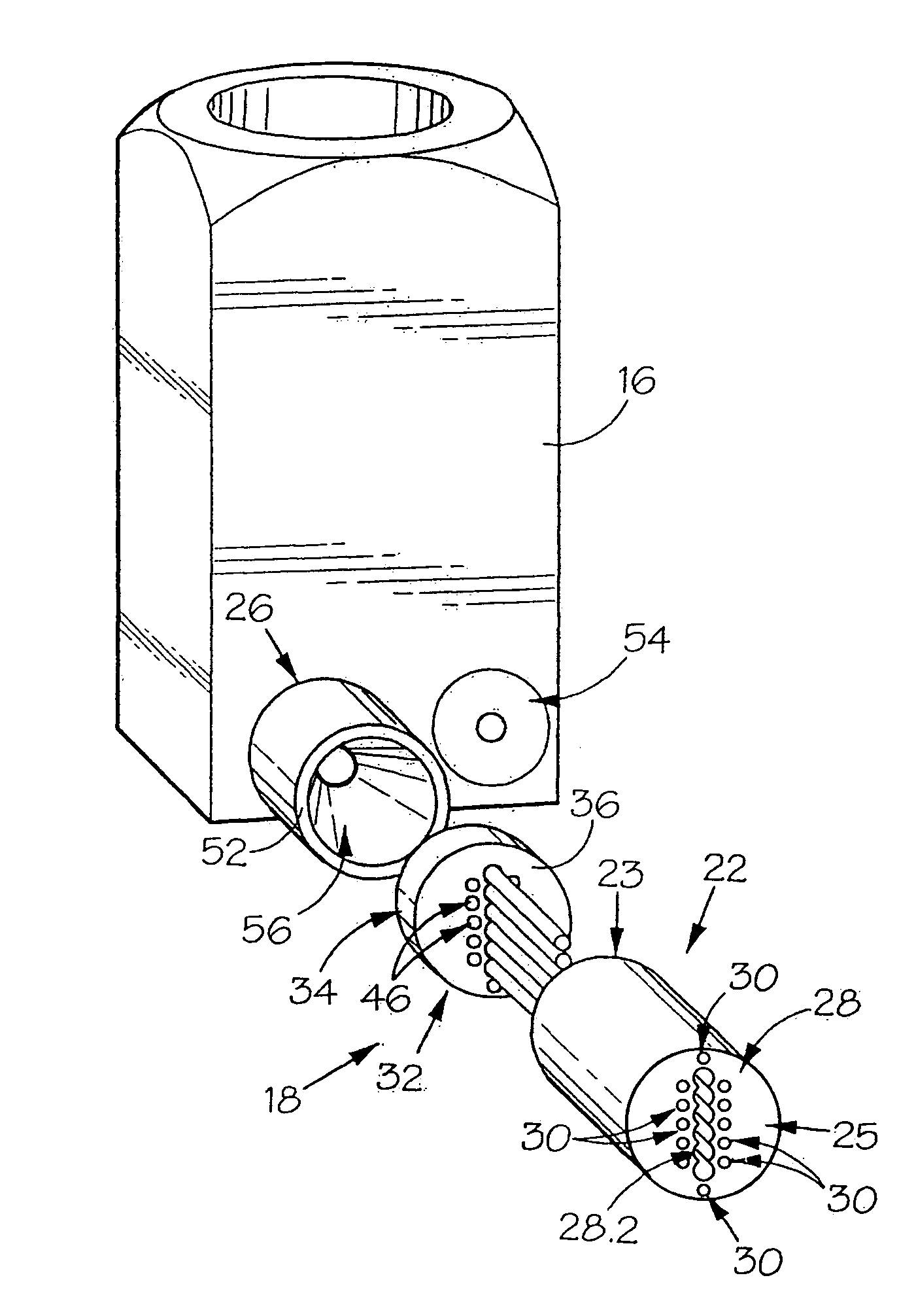
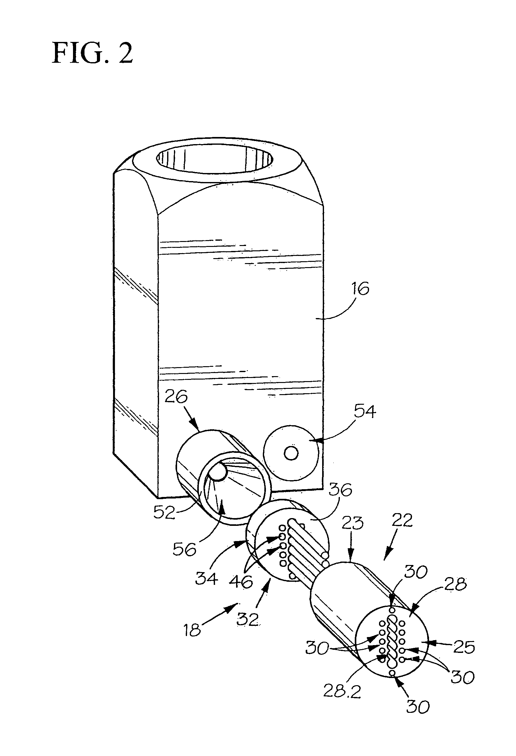
[0060]Referring now also to FIGS. 2 to 4, the casting unit 12 includes a crucible 16 to which a pair of die sets 18, one of which is shown in the drawings, is connectable in flow communication with a chamber 20 defined in the crucible 16.

[0061]Each die set 18 includes a multi-channel die 22, a punch holder 24 and an intermediate die 26.

[0062]The multi-channel die 22 has a cylindrical body and has a pair of ends 23, 25. A hollow portion 28 extends th...


PUM

PropertyMeasurementUnit
grain sizeaaaaaaaaaa
gravityaaaaaaaaaa

Abstract

This manufacturing apparatus for a multi-channel tube having a plurality of parallel channels includes: a crucible; and a die set for forming the multi-channel tube from molten copper supplied from the crucible, the die set including: a hollow portion having an inner surface shaped like the profile of the multi-channel tube; punches which are inserted into the hollow portion from an inlet end of the hollow portion to define a space between the inner surface of the hollow portion and each of the punches; and a feed passage which is disposed between the crucible and the space, and configured to feed the molten copper from the crucible to the space, the molten copper being supplied from the crucible to the space within the die set through the feed passage to solidify as it passes through the hollow portion.

Description

TECHNICAL FIELD[0001]This invention relates to the manufacturing of copper tube. More particularly the invention provides a method of manufacturing multi-channel copper tube. It further relates to apparatus for use in the manufacture of multi-channel copper tube. In addition it relates to tube drawing apparatus. It also relates to multi-channel copper tube.[0002]Priority is claimed on South African Provisional Patent Application No. 2006 / 10521, filed Dec. 14, 2006, the content of which is incorporated herein by reference.BACKGROUND ART[0003]Multi-channel tube is used in numerous applications. One such application is in cooling of electronic components in which multi-channel aluminum tube is used to convey coolant. By virtue of its superior heat transfer properties, it would be preferable to use copper in such applications. However, difficulties are encountered when attempting to manufacture multi-channel tube from copper.[0004]It is an object of this invention to provide means which...

Claims


Application Information

Patent Timeline
Patent Type & Authority Applications(United States)
IPC IPC(8): B32B1/08B22D11/04B22D35/00
CPCB21C1/24B21C37/151B22D11/004B22D11/006B22D11/0406Y10T428/12292B22D11/055B22D11/1206F28F1/022F28F21/085B22C9/08B22D11/045B21C1/16B22D11/00B22D11/04
Inventor MACHET, DAVIDDA CRUZ, ANTONIO RODRIGUESZISERMAN, VLADIMIR SHOILOVICHTAKAGI, KENICHI
Owner MITSUBISHI MATERIALS CORP
Why Eureka
Try Eureka