Bathroom air-conditioner

a technology for air conditioners and bathrooms, applied in lighting and heating apparatus, ventilation systems, heating types, etc., can solve the problems of reducing the efficiency of air conditioners and increasing heat collection, so as to reduce the loss of heat dissipation to the air discharged from the bathroom to the outside, reduce the amount of air blowing, and increase the enthalpy efficiency of radiators.

Active Publication Date: 2010-02-04
PANASONIC INTELLECTUAL PROPERTY MANAGEMENT CO LTD
View PDF12 Cites 17 Cited by
  • Summary
  • Abstract
  • Description
  • Claims
  • Application Information

AI Technical Summary

Benefits of technology

[0015]The heat absorber and a circulating fan, which circulates the air of the bathroom, are placed in the circulating air-course. The radiator and a ventilating fan, which discharges the air of the bathroom to the outdoor, are placed in the ventilating air-course. The heat absorber makes the refrigerant absorb heat from the air in the bathroom, and the radiator makes the refrigerant dissipate heat to the air to be discharged from the bathroom to the outdoor for cooling the bathroom. During this cooling operation, when the temperature of the bathroom becomes lower than a predetermine

Problems solved by technology

In such a case, a part of the heat having undergone the air-conditioning of the bathroom leaks to the out

Method used


Image

  • Bathroom air-conditioner
  • Bathroom air-conditioner
  • Bathroom air-conditioner

Examples


embodiment 1

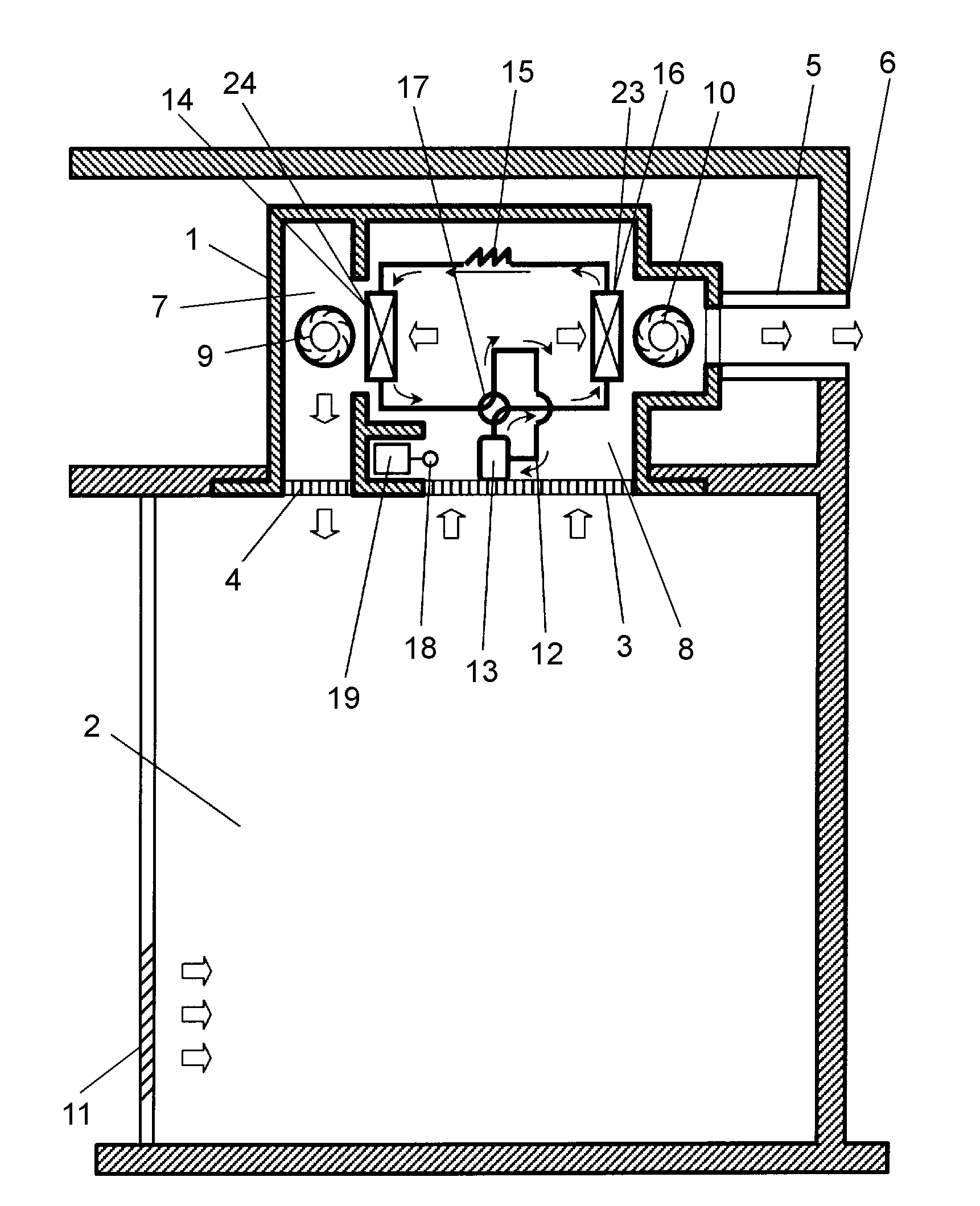
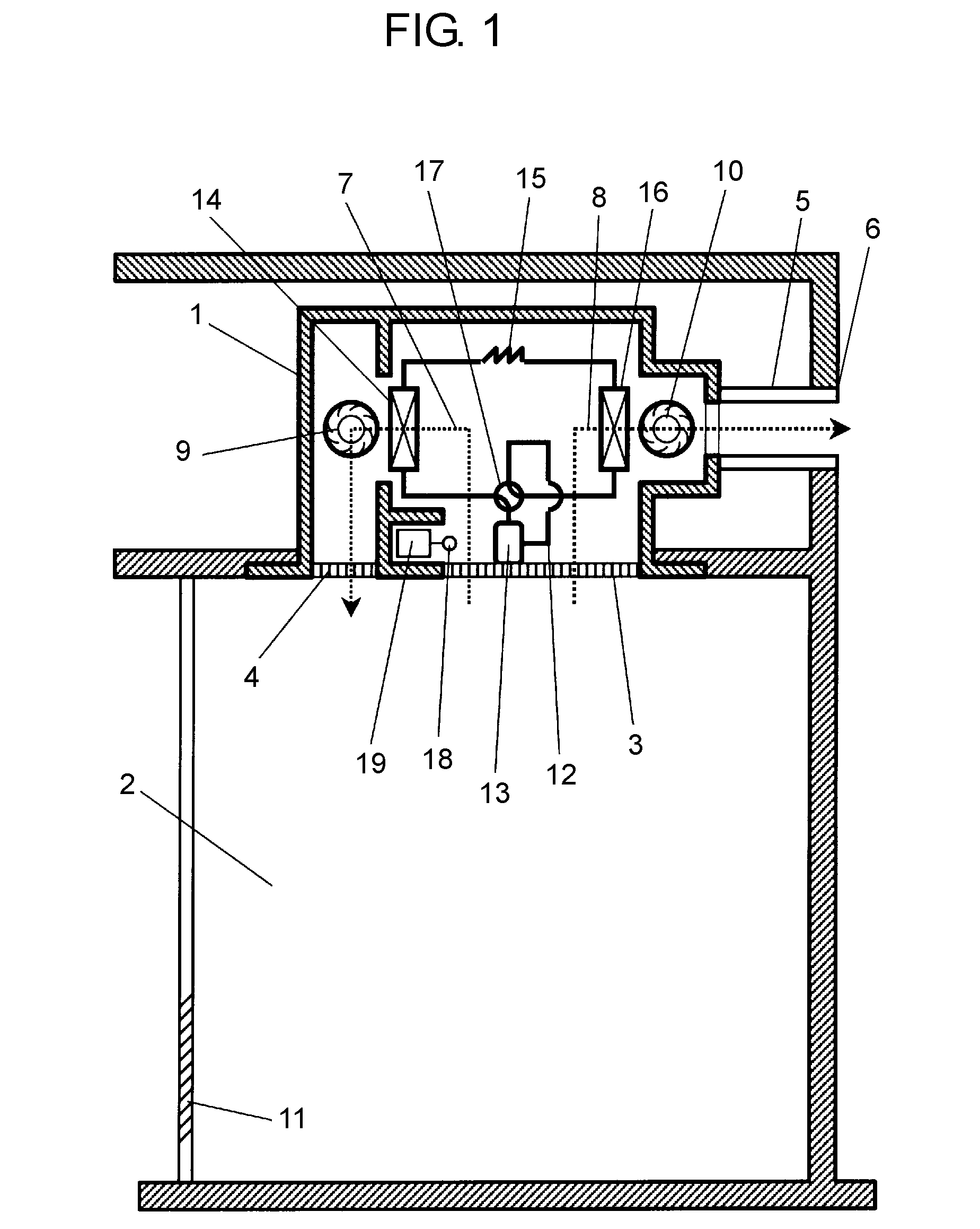
[0048]FIG. 1 shows an air-course and a refrigerant circuit of a bathroom air-conditioner in accordance with the first embodiment of the present invention. As shown in FIG. 1, main unit 1 of the bathroom air-conditioner is placed under the roof of the bathroom, and includes intake port 3 and blowout port 4 open on its underside so that they communicate with bathroom 2. The intake port 3 and blowout port 4 open to bathroom 2 at different places from each other. A first end of evacuating duct 5 is connected to main unit 1, and a second end thereof communicates with outer blowout port 6. Circulating air-course 7 and ventilating air-course 8 are formed in main unit 1, and intake port 3 communicates with blowout port 4 through circulating air-course 7, and sintake port 3 communicates with evacuating duct 5 through ventilating air-course 8. Circulating fan 9 is placed in circulating air-course 7, and ventilating fan 10 is placed in ventilating air-course 8.

[0049]Circulating fan 9 communica...

embodiment 2

[0091]A method of increasing an efficiency of energy is demonstrated hereinafter. This method increases an amount of heat to be collected during the heating operation. FIG. 7 shows schematically a sectional view of a bathroom air-conditioner in accordance with the second embodiment of the present invention.

[0092]The bathroom air-conditioner shown in FIG. 7 differs from that shown in FIG. 5 in the following points: Partition 52 is newly provided for separating circulating air-course 7 from ventilating air-course 8; Compressor 13, decompressing mechanism 15, and controller 54 are placed in ventilating air-course 8; Ventilating fan 10, heat absorber 24 are placed in this order from outer blowout port 6; and no flow-path switching valve is provided because the bathroom air-conditioner shown in FIG. 7 only implements the heating operation.

[0093]The bathroom air-conditioner shown in FIG. 7 comprises the following elements: shutter plate 53 for switching an air-course in ventilating air-co...


PUM


Abstract

A bathroom air-conditioner includes a refrigerant circuit in which a compressor, a radiator, a decompressing mechanism and a heat absorber are connected with one another through a pipe, a circulating air-course, and a ventilating air-course. In the circulating air-course, the radiator and a circulating fan for circulating the air of the bathroom are placed. In the ventilating air-course, the heat absorber and a ventilating fan for discharging the air from the bathroom to the outside are placed. The heat absorber makes the refrigerant absorb heat from the air of the bathroom, and the radiator makes the refrigerant dissipate heat to the air of the bathroom for heating the bathroom. During the heating of the bathroom, when a temperature of the bathroom becomes higher than a given temperature, a controller reduces an air-blow amount from the ventilating fan.

Description

TECHNICAL FIELD[0001]The present invention relates to a bathroom air-conditioner for air-conditioning a bathroom by using a heat pump.BACKGROUND ART[0002]A conventional bathroom air-conditioner using a heat pump has worked this way: A first heat exchanger of the heat pump radiates or absorbs heat to / from the air drawn from the outside of the bathroom, and then blows out the air into the bathroom. A second heat exchanger of the heat pump absorbs or radiates heat from / to air evacuated from the bathroom to the outdoors. The bathroom has been thus air-conditioned (refer to, e.g. Patent Document 1).[0003]The foregoing air-conditioner collects the heat from the air to be discharged from the bathroom to the outdoor, and gives heat to another air drawn from a place other than the bathroom, thereby air-conditioning the bathroom. A continuous operation of this air-conditioner sometimes generates a difference in enthalpy between the air drawn from a place other than the bathroom and the air in...

Claims


Application Information

Patent Timeline
IPC IPC(8): E03D9/04F25B1/00F24F13/10
CPCF24D5/04F24D5/12F24D15/04F24D2200/12F24D2200/22Y02B30/563F24F12/003F24F2007/001Y02B10/70Y02B30/52F24F11/0001Y02B30/13Y02B30/56Y02B30/12
Inventor KATSUMI, YOSHIMASANISHIZURU, YOSHIHIROSAITOU, KAZUHIROMATUBARA, MITUNORITSUBOUCHI, MASAFUMISUGATA, YUUJITSUIHIJI, HIROSHI
Owner PANASONIC INTELLECTUAL PROPERTY MANAGEMENT CO LTD
Why Eureka
Try Eureka