Pallet

Active Publication Date: 2010-03-11
KYORAKU CO LTD
View PDF17 Cites 6 Cited by
  • Summary
  • Abstract
  • Description
  • Claims
  • Application Information

AI Technical Summary

Benefits of technology

[0019]In a pallet according to the present invention, in the manufacturing process thereof, blades are respectively thrust on a parison from both sides thereof, and portions of the parison are fused in the middle of a hollow portion, to form inner ribs. Therefore, the extension amount of resin moved by the blades can be minimized. Particularly, the blade including a longitudinal blade and a transverse blade that form inner ribs arranged in cross directions and a cross blade forming an intersection portion in a solid shape positioned at an intersection of the inner ribs spaced apart from each other is used, which can prevent the break of the parison as much as possible in manufacturing the pallet.
[0020]Furthermore, the blades are only thrust on the parison more shallowly than those in the conventional example so that the inner ribs are formed. Therefore, the wall thickness of the formed inner rib becomes larger than that of the conventional inner rib. Particularly, the wall thickness of the inner rib can be increased at a position, at the center in the height direction of the inner rib, where an end surface of a first inner rib and an end surface of a second inner rib are welded to each other. As a result, t

Problems solved by technology

When the distance between the first wall and the second wall is widened, and the pitch between the adjacent inner ribs is narrowed, however, the parison is greatly extended by the blade, and partic

Method used


Image

  • Pallet
  • Pallet
  • Pallet

Examples


Example

[0032]10 pallet

[0033]11 mounting groove

[0034]11a relief hole

[0035]12 leg

[0036]13 first wall

[0037]13a first inner rib

[0038]13b first inner rib

[0039]14 second wall

[0040]14a second inner rib

[0041]14b second inner rib

[0042]15 intersection portion

[0043]20 sleeve

[0044]30 cover unit

[0045]40 fixing unit

[0046]41 hook member

[0047]41a hook

[0048]42 relief hole

[0049]50 parison

[0050]60 split mold

[0051]70 movable blade

[0052]7a longitudinal blade

[0053]7b transverse blade

[0054]7c cross blade

[0055]80 recess

[0056]A transport container

[0057]H void portion

[0058]S fork insertion opening

[0059]V hollow portion

BEST MODE FOR CARRYING OUT THE INVENTION

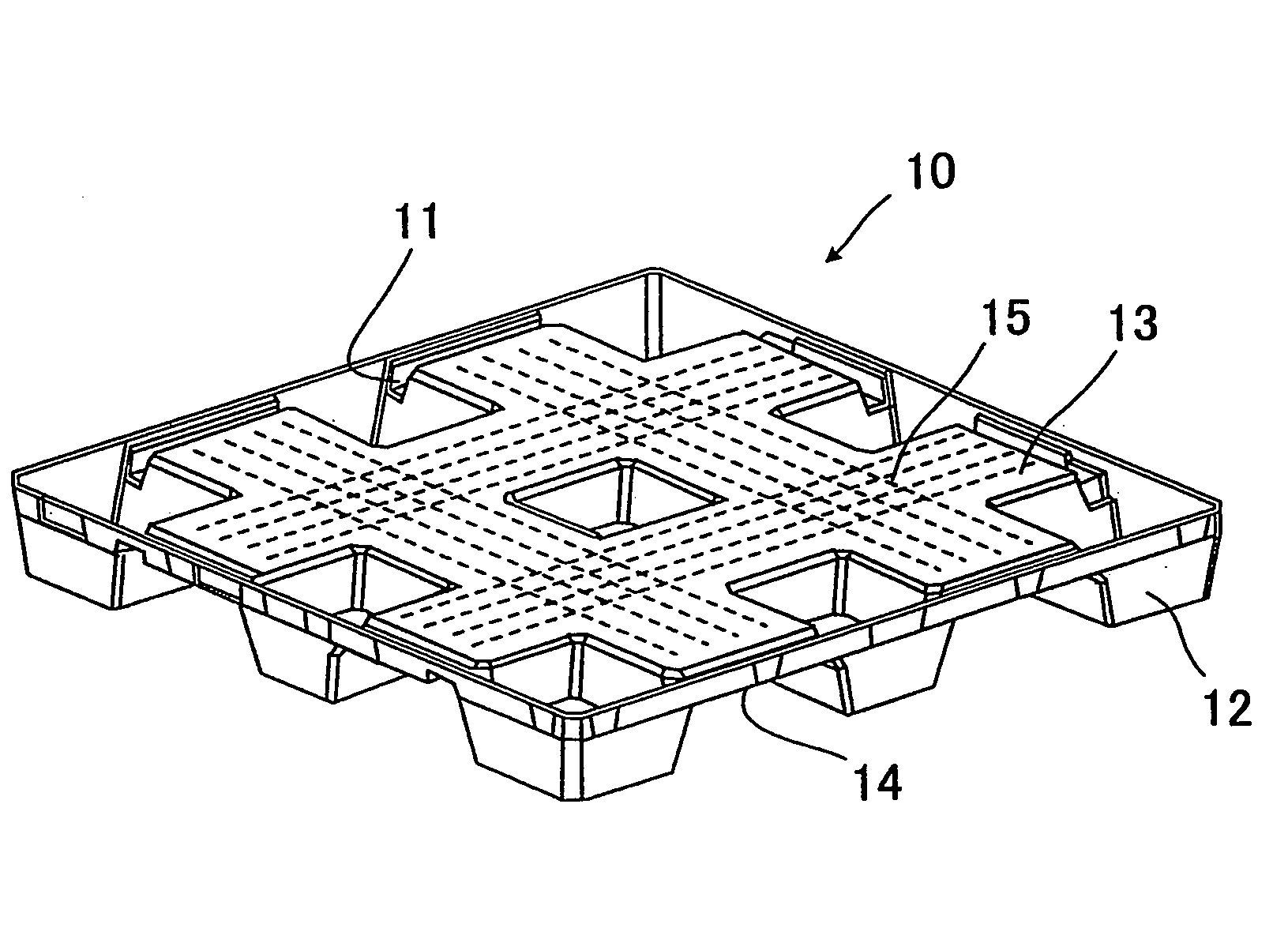
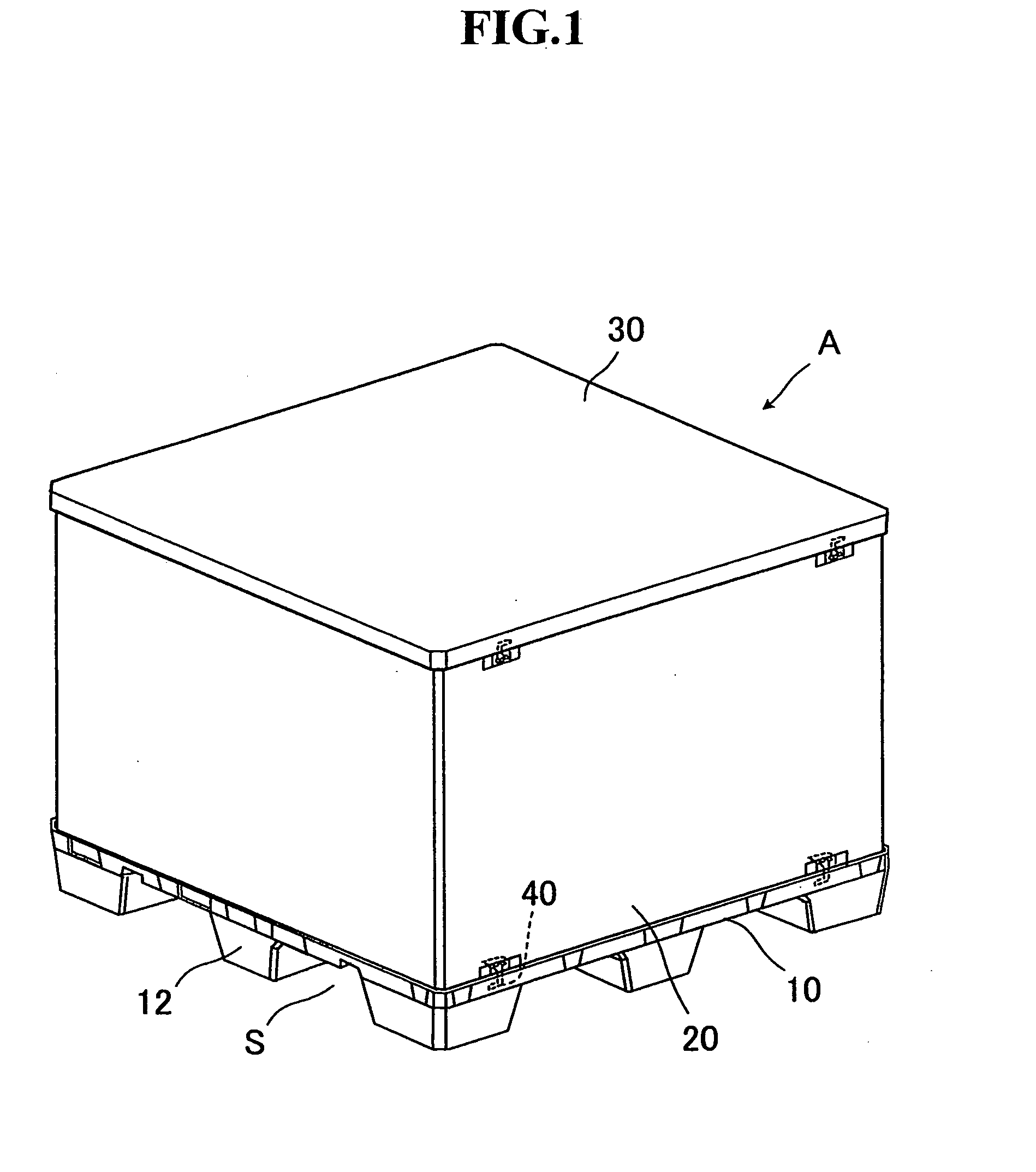
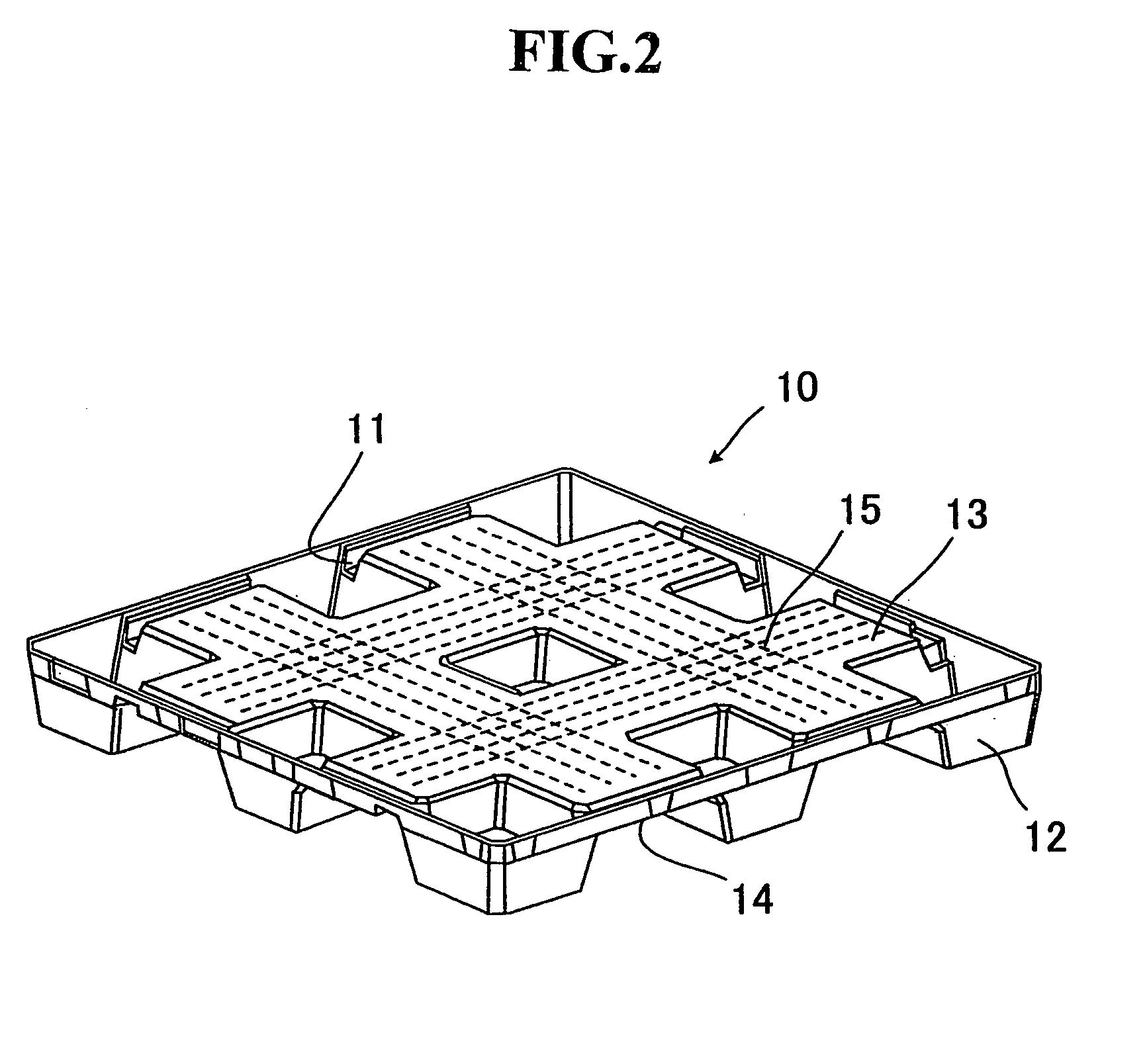
[0060]An embodiment of the present invention will be described with reference to the drawings. FIG. 1 illustrates an example of a transport container using a pallet according to the present embodiment. FIG. 2 illustrates the pallet according to the present embodiment. A transport container A in which a pallet is incorporated will be first described. As illustrat...


PUM

PropertyMeasurementUnit
Distanceaaaaaaaaaa
Thicknessaaaaaaaaaa
Bending strengthaaaaaaaaaa

Abstract

Problem to be Solved
The present invention is directed to providing a pallet having a large thickness, having inner ribs not easily broken formed therein, and having high bending strength.
Solution
A pallet 10 having a hollow double-walled structure formed by blow molding includes a first wall 13 on which a cargo is placed, a second wall 14 spaced apart from the first wall 13 by a predetermined distance, and inner ribs that connect the first wall 13 and the second wall 14. In the pallet 10, the inner ribs are respectively formed by continuously abutting and integrating end surfaces of first inner ribs 13a and 13b projecting from the first wall 13 toward a hollow portion and end surfaces of second inner ribs 14a and 14b projecting from the second wall 14 toward the hollow portion.

Description

TECHNICAL FIELD[0001]The present invention relates to a pallet for conveyance and a pallet for a transport container having inner ribs formed in a hollow portion of its inner part.BACKGROUND ART[0002]Conventionally, in order to efficiently convey cargos, pallets for conveyance or transport containers have been used. As such pallets, a pallet being lightweight and having high bending strength has been developed by partially forming cross-shaped inner ribs, centered around a post composed of a recess, inside a cargo mounting stand with a hollow double-walled structure (see Patent Document 1).[0003]A pallet with a hollow double-walled structure exhibits great bending strength for bending stresses in all directions applied when supported by a fork lift or the like by forming cross-shaped inner ribs within a hollow portion of the pallet. This pallet with a hollow double-walled structure is mainly manufactured by blow molding.[0004]A method for manufacturing the pallet with a hollow doubl...

Claims


Application Information

Patent Timeline
IPC IPC(8): B65D19/32B65D19/22
CPCB29C49/04B29C49/4802B29C2049/4807B29L2031/7178B65D19/004B65D2519/00034B65D2519/00711B65D2519/00268B65D2519/00288B65D2519/00318B65D2519/00412B65D2519/00572B65D2519/00069
Inventor ENDO, HARUHIRO
Owner KYORAKU CO LTD
Why Eureka
Try Eureka