

Deburring tool
- Summary
- Abstract
- Description
- Claims
- Application Information
AI Technical Summary
Benefits of technology
Problems solved by technology
Method used
Image

Examples
first embodiment
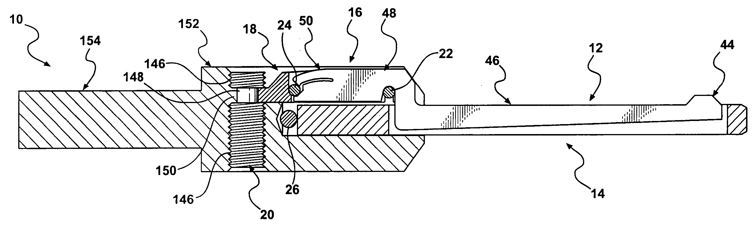
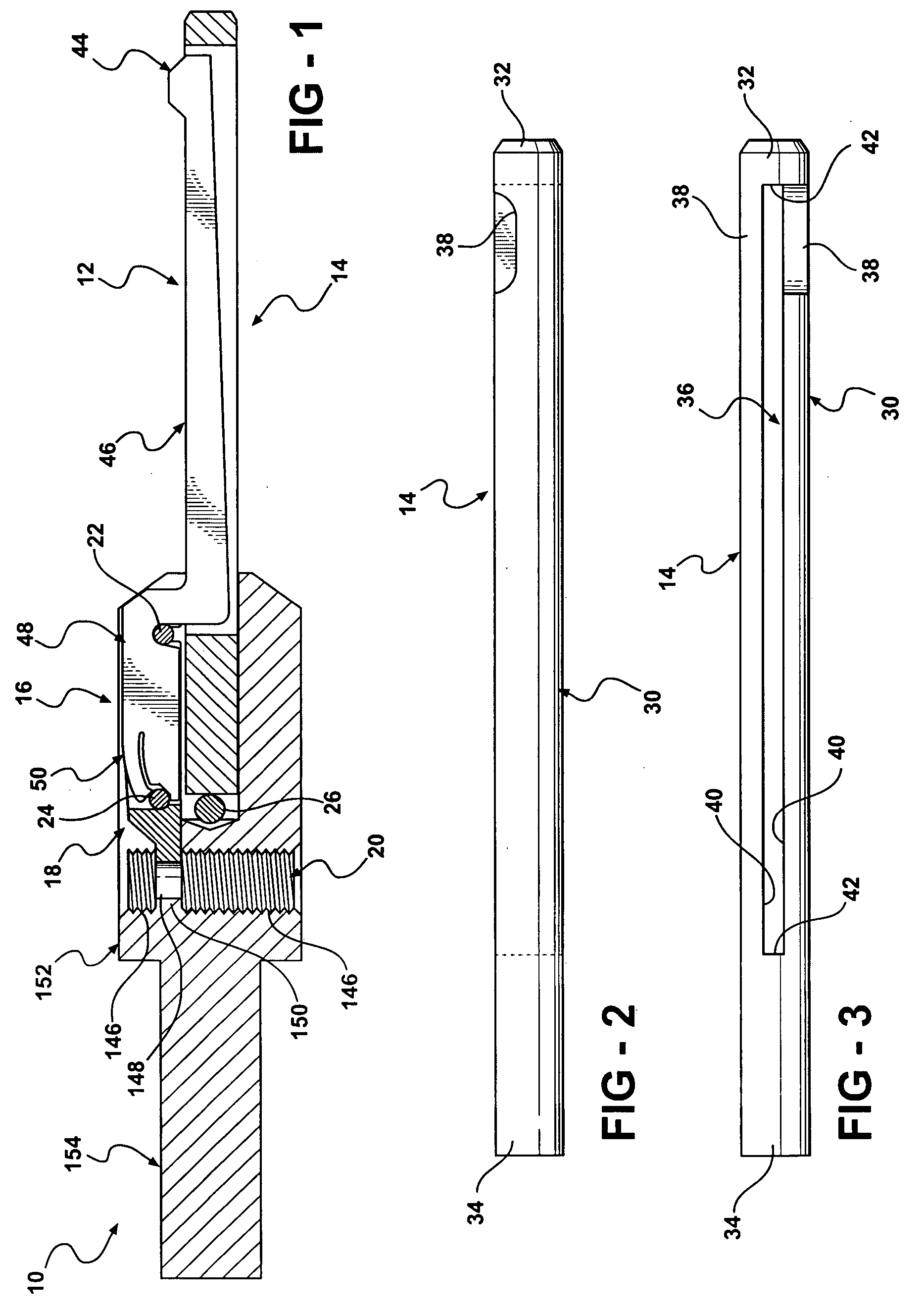
[0087] Referring now to FIGS. 1-12, in the deburring tool 10, the blade 12 includes a clip portion, generally indicated at 50, and the holder 16 is adapted to support a pivot cradle, generally indicated at 18, and an adjusting member, generally indicated at 20. Each of the clip portion 50, holder 16, pivot cradle 18, and adjusting member 20 is described in detail below. Since, as shown in FIGS. 13-18, the blade 212, 412 has the clip portion 250, 450 as well, the clip portion 250, 450 will now be described with reference to the clip portion 50.
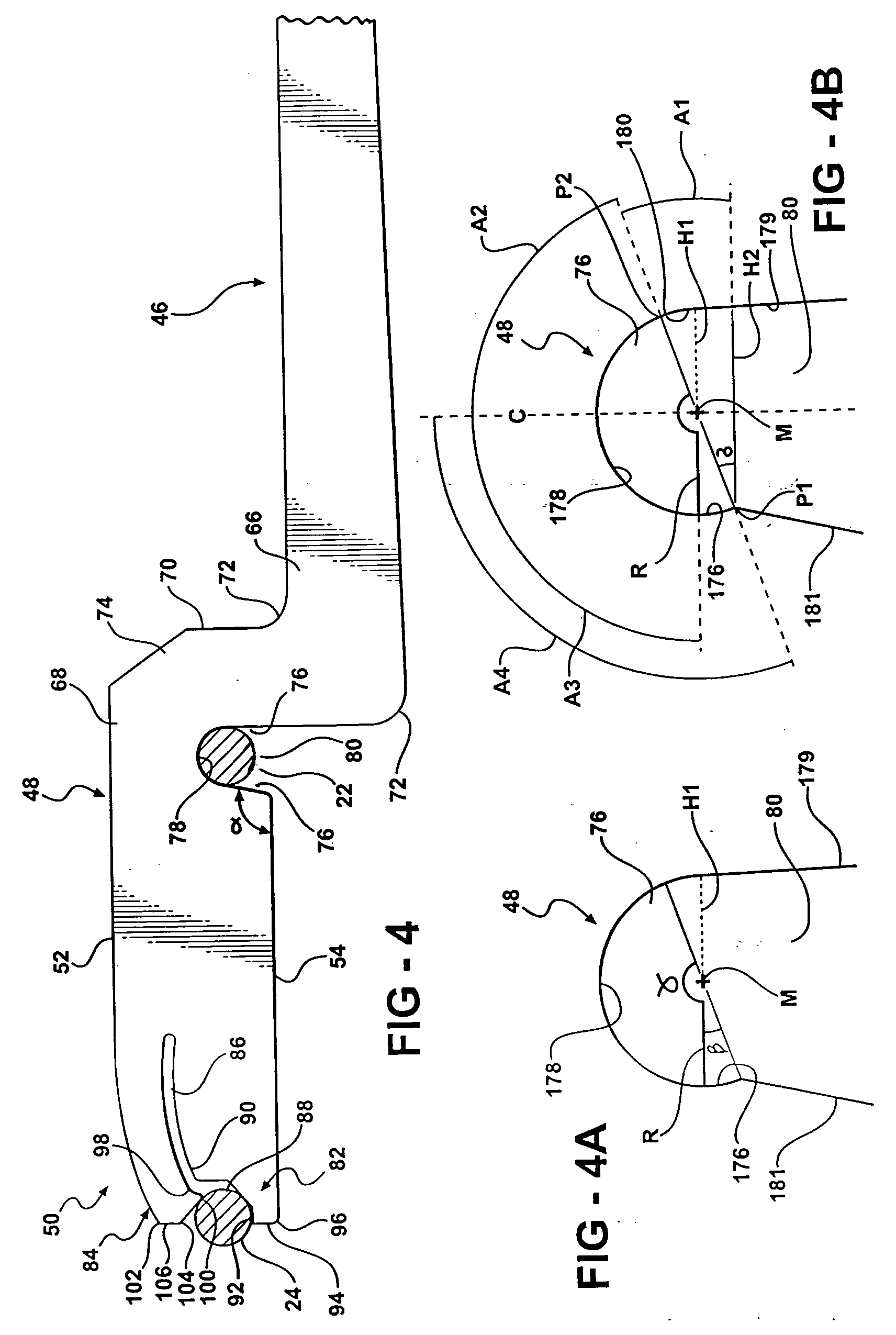
[0088] The clip portion 50 extends integrally from the retaining portion 48 and defined substantially at the end of the blade 12 disposed opposite the head portion 44 of the blade 12. The clip portion 50 is adapted to flex to provide a spring-like force acting along the blade 12 toward the head portion 44 to facilitate insertion and removal of the blade 12 relative to the deburring tool 10 without use of any tools.
[0089] As shown in FIGS. 1 an...
second embodiment
[0125] Referring now to FIGS. 13-15, where like numerals increased by 200 are used to represent structure like that of the deburring tool 10, a deburring tool of the present invention, generally indicated at 210, is shown. The holder 216 is adapted to support a clip pin 224 within the holder 216. Accordingly, the holder 216 includes a clip-pin hole 382. Unlike the adjustable-position deburring tool 10, the fixed-position deburring tool 210 does not include an adjusting member and a pivot cradle.
[0126] Just as with the deburring tool 10, as the upper jaw 284 is activated by a hand of an operator of the deburring tool 210, for instance, the blade 212 is forced forward, or in a direction toward the head portion 244, resulting in the retention pin 222 retaining the retaining portion 248. Conversely, when the blade 212 is forced rearward, or in a direction toward the clip portion 250, the retaining portion 248 is released from the retention pin 222, thus allowing for removal of the blade...
third embodiment
[0128] Referring now to FIGS. 16-18, where like numerals increased by 400 are used to represent structure like that of the deburring tool 10, a deburring tool of the present invention, generally indicated at 410, is shown. Unlike the adjustable-position deburring tool 10, the fixed-position deburring tool 410 does not include an adjusting member and a pivot cradle. Unlike both the deburring tool 10 and fixed-position deburring tool 210, the deburring tool 410 does not include a holder. As such, unlike the arbors 14, 214, the arbor 414 is not fastened in a holder. Rather, the arbor 414 is fastened in the chuck of the drive motor, for instance, and, thus, cannot be changed or adjusted absent removal of the arbor 414 from the chuck. In this way, the arbor 414 is essentially a disposable tool. The arbor 414 is adapted to receive the retention pin 422 and the clip pin 424 and, thus, further includes a retention-pin hole 570 and a clip-pin hole 582. Unlike the blade 12, 212, the blade 412...
PUM
| Property | Measurement | Unit |
|---|---|---|
| Force | aaaaa | aaaaa |
| Electrical resistance | aaaaa | aaaaa |
| Flexibility | aaaaa | aaaaa |
Abstract
Description
Claims
Application Information